
|
|
Forum Index : Electronics : Electrical Math, Argh!
| Page 1 of 2 |
|||||
| Author | Message | ||||
| Ironmaiden Regular Member Joined: 09/07/2019 Location: United StatesPosts: 53 |
Got a question for someone who is a math wiz? In Nigel Smith's book there are formula's for calculating capacitors for induction generators. http://www.fastonline.org/CD3WD_40/JF/JF_OTHER/BIG/Motors%20as%20Generators%20-%20N.%20Smith,%20%20ITDG%20UK%201994.pdf I figured out the full load slip equation with no issues. However, How do I work the capacitor calculation on page 36??? The bottom part of the equation is what is causing me all the grief. What do the symbols mean exactly? I was never very good at math in school and still suck at it. Nigel's book was written in British math. I am trying to figure out these equations in the fashion we are taught as Americans in school on my old Texas Instruments Ti-83 Plus calculator. Robert Edited 2019-08-10 13:18 by Ironmaiden |
||||
| poida Guru Joined: 02/02/2017 Location: AustraliaPosts: 1480 |
This is what I see as page 36 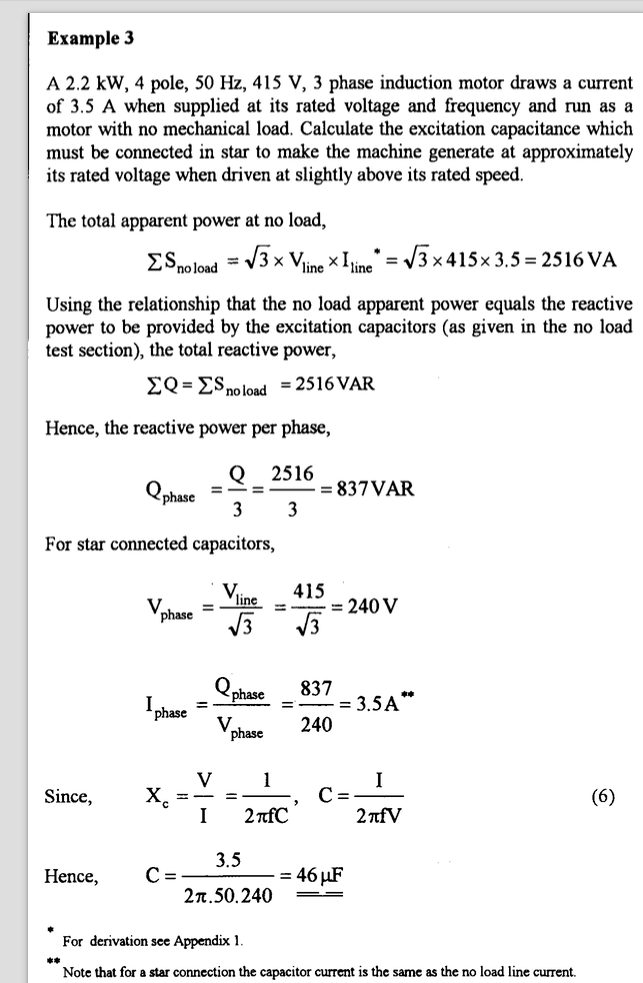 I think you want to know the capacitor needed. The second last line produces the final equation to use when you already know the current and the AC voltage. In this case, he uses 3.5A as the current and 240V as the voltage. 50Hz is the frequency. He then plugs these 3 values into the last line's equation. C = 3.5 / (3.142 x 2.0 x 50 x 240) = 47uF I assume you have obtained the current for your situation? You would use 60Hz and 120V, and just do the above calcs. wronger than a phone book full of wrong phone numbers |
||||
| Ironmaiden Regular Member Joined: 09/07/2019 Location: United StatesPosts: 53 |
poida, You are a magician. I wish they had just wrote the equation like you did there. I most likely will have many more questions as I work through the book. Now I need to remember how to work this old calculator. I keep getting 4.5uf. I haven't used this thing in over a decade. My motor is 14 amps at 208 volts and is a 5HP 3 phase machine rated for 208/230/460v AC. The amps go down as the V increases. I am figuring the caps for both Wye and Delta at 208 volts. I get 120v from any phase to neutral or the star point depending on how you know the setup.I really should just figure for 240 volts since I will be seeing 230/240 in operation as a generator. Speed needed for 60hz will pretty much determine that the voltage is going to be greater than 208v. Robert Edited 2019-08-10 15:01 by Ironmaiden |
||||
| Davo99 Guru Joined: 03/06/2019 Location: AustraliaPosts: 1585 |
I read that paper so many years ago and so long since I played with this stuff I have forgotten 80% of it. I am confused here as to what you are trying to do? As for trying to figure out star and delta, they are going to be so different in the required gearing ( Pulley ratio) that you will only want to bother with one. Changing the caps is not going to be enough to allow both configurations to run happily unless you have a way over sized engine capeable of delivering the required mechanical power way down it's rev range of one and be running fast to be in the sweet spot for the other... and then you still have the Frequency issue if that is a factor. For Incandescent bulbs and heating elements, does not matter at all. For other things you need to pay attention to the gearing and the caps. How are you wiring this up? As 3 or single phase? As you are saying you want to wire it for 240 and you are getting 120 from each leg, it sounds like you are trying to do it single or C2C. For a 4Kw ( 5 Hp ) motor you want around 20 UF on the first pair of legs,40 on the second and none on the 3rd. I buy 3x 20 UF caps because 20's are a lot easier and cheaper to buy where I am than 40's and don't forget you want 450-500V RUN caps not starting caps. That also allows you to put 10 Uf on the first leg and 20 on the second if you want to change from star to delta just by changing the caps from a series to a parallel configuration. If you have a 20 and a 40 cap, you are a cap short of you want to change run them in series to decrease the value. But this is very much an inexact science. The faster you turn the motor the less capacitance you need but the more sensitive the thing will be to crashing the field with switched loads. The more load you put on it the more capacitance you are better off with and more capacitance also allows the field in the windings to build easier. The cap ratings are more of a guide than a hard and fast and there is a pretty wide tolerance. As IMAGS are far more happy with Resistive than Inductive loads and intermittent loads are a real pain for these things, I usually spin them up with the load connected and trim RPM to give me the voltage I want from there. I have run 10 UF and 40 Uf on the same setup and either will work depending on how hard you want to drive the motor and if you are trying to get the frequency right. In my experience, getting the frequency AND the voltage accurate is not an easy task at all. I myself won't bother with an IMAG of only 5 HP for any intermittent loads even with a decent constant load. The reactive power simply isn't there. The 12 Kw IMAG I have is far more tolerant to loads switching in and out and also has a much better useable output. For stability and Frequency/ voltage matching, I found rating the motor as a generator is far better at half nameplate output and a lot of these papers seem VERY optimistic in what they say the motors can be driven to. One way around the switched load sensitivity is to set up your Imag with a base capacitance and then put additional capacitance on each load. When said load is switched in, the increased capacitance connected to it balances it's draw and stops the Field on the IMAG crashing when it kicks in and the voltage going stupid High when it kicks out. 47 Uf sounds way high to me for a motor of this size even though I'm used to playing with a lower frequency. If I were getting pedantic, I'd be suggesting 15 Uf on the first cap and 30 on the second but I think 20UF gives more wiggle room and allows a bit higher loading without the IMAG getting too finicky. Remember to disconnect your load before you shut the IMAG down or you'll have to reflash the windings. I found with the engine I was using on my setup which was over driving the IMAG, I could just give it a big Rev and the windings would re energise. Be interested to hear more about your project and what you intend to do with it. What engine will you be driving the IMAG with? |
||||
| Warpspeed Guru Joined: 09/08/2007 Location: AustraliaPosts: 4406 |
I messed with this briefly and decided that although its "interesting" its also pretty useless for anything practical. Yes you can design a system that works at a precise rpm, and voltage and load, provided you know all of the magnetic parameters of the machine. But what if your rpm or load varies? What if the voltage goes to double, or falls to one quarter ? Is it then still useful for anything ? I will tell you now what happens. You fit your resonating capacitors, and slowly increase the drive rpm. Nothing much happens until you get very close to the LC resonant frequency. The voltage very suddenly (instantly) rises up to some huge peak, limited only by the onset of magnetic saturation. The load on the mechanical driver suddenly increases too. So you have maybe 480 volts at 37Hz or 480 Hz or whatever it turns out to be. You can then start loading it up, and the voltage starts to fall. Its something like a solar panel, in that there is a critical maximum power loading point. Any extra loading and the output of the machine collapses back to almost nothing. About the only useful application for this is charging a battery, where the output voltage is very closely controlled and limited by the voltage of the battery. It has absolutely no application for driving a resistive load, or any load that can change unless you can accept very wild voltage swings. That article mentions building very high power shunt voltage regulators to keep a constant load on the machine. Very necessary ! If you have a 5Kw machine and you want to run a 100 watt light globe, you may need to dissipate 4,900 watts in the shunt regulator. Not very practical or efficient, unless the mechanical power to drive it is is free. Anyhow have some fun, and tell us about your results. Cheers, �Tony. |
||||
| Davo99 Guru Joined: 03/06/2019 Location: AustraliaPosts: 1585 |
have to disagree with that Tony. I have used them and I'd say resistive loads are these things forte. No, you wouldn't want to try driving a 100W light bulb but a couple of Kw from a 5 Kw motor, easy. I also hooked mine up to a GTI through a rectifier. Yes, the GTI made the engine hunt a bit but it certainly worked and worked well. Yes, they can be peaky or fragile as well but you can manage that especially with a constant resistive load. I have found with the small amount of testing I have done so far on my 12KW motor that the bigger motor is also far more stable than the smaller motors. Thing weighs 170 KG so has a lot of reactive power. Want to run your house off one? Forget it. Want to run a water heater, GTI or run one grid coupled to offset power usage, very practical. It also helps to have a large driving motor as well which will also help with the reactive power and absorb switched loads better. |
||||
| Ironmaiden Regular Member Joined: 09/07/2019 Location: United StatesPosts: 53 |
Gentlemen, Ladies, What I am trying to do is calculate the capacitance needed for my 4KW induction generator at the 240v level. We are blessed or cursed with the Edison 3 wire system. I get my 120v from one half of one set of coils to neutral and the other half from the other set of coils to neutral. My machine is Star connected and has the 9 leads in the junction box. I have found what I believe is a workable drawing for a C-2C arrangement on a star connected induction motor? https://www.researchgate.net/figure/Connection-diagram-of-the-single-phase-induction-generator_fig1_3270780 I wish I knew what the equation numbers were for that setup. They want $37 for the paper to read the whole thing.  I have thought about breaking open the motor and fetch out the ends of wires 10, 11, 12 so I can connect for a low delta C-2C 120v only single phase output. I might still do that modification if the star C-2C setup proves a failure. Sparweb did the mod on a Baldor motor smaller than mine. http://www.sparweb.ca/3_Gen_MoCo/Baldy.html I would like to be able to run the fridge and freezer, some lights and the TV. Or maybe the microwave oven or a toaster oven, electric kettle or electric hot plate when the grid is down. Power is a 5HP Briggs & Stratton I/C commercial engine. Means it has the steel cylinder liner for longevity. I had wanted to get a 7.5HP 3 phase motor for 5.5KW but haven't found one I can afford. Most of them cost more than both of my backup generators. One a Coleman and the other a Homelite. Robert Edited 2019-08-11 05:43 by Ironmaiden |
||||
| Warpspeed Guru Joined: 09/08/2007 Location: AustraliaPosts: 4406 |
O/k understood. There are two ways to attack this problem, the hands on cut and try method, or the purely theoretical mathematical approach. The mathematical approach only works if you know what the magnetic constants are of the motor to plug into your equations. To get those numbers you will need to carry out some practical tests and make some measurements. So you are really reverting back to the suck it and see hands on practical method. What we are dealing here is with ferroresonance. Ferroresonance is different to normal LC resonance because the inductance can and usually is highly non linear, as it is driven hard into magnetic saturation. Normal LC resonance assumes that the inductance s linear and never changes, and the result is a pure easily calculated sine wave of easily calculated frequency. Ferroresonance can be very useful, but its a very different beast. What happens is there will be an iron cored inductor with a parallel capacitor. When this circuit is excited with external energy, a circulating current very quickly builds up in amplitude, driving the iron core into magnetic saturation in either direction. That will naturally limit the amplitude build up, and you get a constant voltage and circulating current that also maintains a constant amplitude. The frequency at which this ferroresonance occurs is determined by the capacitance and the non linear inductive characteristics of the windings and core. If you study Faraday's transformer laws, flux density in the core is determined both by voltage, frequency and core cross section, and its the final flux density at saturation that determines both the voltage and frequency at which ferroresonance occurs. We can do nothing about the magnetic part of our machine, all we can do is change the tuning capacitors. So we start out with some experimental value of capacitance and we then increase the rpm until we very suddenly hit ferroresonance and there is a massive buildup of energy. We then note the frequency and the voltage. Larger capacitors will produce a lower voltage at a lower resonant frequency. As with any transformer, if you lower the drive frequency it will reach magnetic saturation at a lower applied voltage. Smaller capacitors increase both voltage at resonance, and the frequency at which resonance occurs. Now you will find that your off the shelf machine is designed for a certain voltage and frequency (say 120v 60Hz) and its designed to work safely below full hard magnetic saturation. If you use the same machine in the ferroresonant condition it will produce either a higher voltage at full saturation, or you must tune it and run it at less than 60Hz to reduce the voltage to 120v. Or you may be able to run it at both 120v and 60Hz with a very carefully selected load level. How you set this up depends on what you want. If its for a heating element, the frequency probably not important. Now once we have chosen suitable tuning capacitors to run at our required speed and voltage, we can tap off "some" of the circulating resonant energy. That will cause the voltage to fall by quite a lot. If we try to draw off too much energy the voltage will collapse and ferroresonance will suddenly cease. So we need to juggle our rpm, voltage, and load experimentally until we reach a desired compromise, using the tuning capacitors as our only tuning tool. Once you have achieved all of this, and determined an actual operating point, the math can then be applied to select a different operating point that may be more suitable. There is no simple way to apply math to a completely unknown machine with any success. You will need to do some initial experimental testing and work from that basis. Cheers, �Tony. |
||||
| Davo99 Guru Joined: 03/06/2019 Location: AustraliaPosts: 1585 |
What you are wanting and trying to do is not feasible and you are not understanding what you are playing with here. There is NO " setting it up for 240V level". It's NOT a generator that has some sort of Field control to vary it's output like a proper generator with an AVR or other means of regulating the field strength. The only way to do that is as Tony said which is to run the thing flat out, tap off the power you want and divert the rest to a dump ( waste) Load. As I said, if you want to run your house of one of these, FORGET IT! Fridges and freezers are 2 of the most difficult loads for these because as I also said, switching loads in and out is difficult for these setups. Yes, you can as I said put the capacitance on the load which will help but there are still a LOT of limitations. Your first statement of wanting to set it up for 240V level is flawed and I'm sorry to say, illustrated you don't understand what you are dealing with. You want to set it up for 240V level at what amperage/ output? the setup for 240V while running the TV will be different to running the fridge and MILES different to running the kettle and the hotplate and different for every single combination! This is NOT a normal generator, it's a MOTOR that's converted and as such it will not allow you to just add some caps and run what ever loads you want at 240V or anything else. As that is what your needs seem to run to, buy a proper GENERATOR head or a complete generator setup because an IMAG is not a soloution to your needs and desires. If You have your hotplate or kettle running with the TV or microwave and the Kettle kicks out, it's going to likely blow the snot out the microwave when the Voltage spikes. That's assuming you can get them all started without crashing the field in the first place. that would require you start one and then increase the motor speed, add more capacitance or manage the varying loads in some other way. Again, the only way you can do this is to have a load diverter on the thing to start with. IF you are thinking that you just need to add caps to get the thing to output 240V and then plug in whatever you like and it will run just fine like a generator, You are WRONG and not understanding how these things work. If you are not going to build a diverter and running the appliances you noted is what you will do with the thing, then forget it before you start. It wont work and if you get it working, it will likely blow the crap out of something. I'm not trying to give you the typical High and Mighty puritan Internet highbrow attitude here, I'm telling you in straight, basic terms... as Tony has tried to also tell you which I completely agree with in what you are wanting to do with the thing. It wont work unless you have a load diverter to couple to it. Also again, I recommend caps that are 20UF but they are going to vary depending on load. There is no set size to get 240V whether the thing is running a TV or a hotplate or a fridge. These things DO not work that way. They are variable, Finicky and the minute you change loads you need to adjust something on them. They are not an AVR controlled generator and the difference is they do not have the ability to control the magnetic strength as a genny does. 5.5 out of a 7.5 Kw Motor? Yeah good luck with that no matter what the books and papers say. You will be able to get it but at what frequency and voltage.... Ya! And the second you change the load from 5.5 Kw to 5KW, you'll be doing 400V and 80Hz. For what you want, BUY A GENERATOR. IMAGS can be a cheap and cheerful way of making power in some applications but not what you want without a lot of complication that makes them a poor choice for what you want to do and not worth your time, money inevitable frustration and ruined appliances. |
||||
| Warpspeed Guru Joined: 09/08/2007 Location: AustraliaPosts: 4406 |
Davo is 100% correct. Cheers, �Tony. |
||||
| Ironmaiden Regular Member Joined: 09/07/2019 Location: United StatesPosts: 53 |
Crickey! There is some harsh responses here. First off, I have two proper generators. These Imag setups are a science experiment. Being driven from a constant speed prime mover should, in theory eliminate some of the frequency stability issues. The voltage and frequency issues can also be addressed by having circuits that regulate by switching in and out caps as needed. Cap switching can be done by a controller IGC/ELC or through a dedicated circuit design. I've noted several controller designs including voltage sensing relays that could switch the caps in and out to regulate the Imag. One would have to find the smallest amount of capacitance to get the motor excited and stable to power the control circuits. The rest of the capacitance needed would be switched by the controller depending on the load and it's influence on the Imag's output voltage and frequency. I left this site once before due to hostilities. About at that point again.  I've had my motor generating 120v and 62hz connecting the caps in delta on the star connected windings. The output was limited to a 1000 watts per phase to neutral. C-2C would give the full output as single phase but is harder to setup and get working stability being tricky with these things. Robert |
||||
| Warpspeed Guru Joined: 09/08/2007 Location: AustraliaPosts: 4406 |
[quote] harder to setup and get working stability being tricky with these things.[/quote] You will never have working stability, that is the whole problem. Even the slightest change in rpm or load will produce massive voltage swings. Onset of ferroresonance is very sudden and violent, and collapse of ferroresonance is also very sudden. All this does not matter when charging a battery, because the battery stabilizes the voltage. Or with a heating element that presents a constant ohmic load, and the voltage and frequency are not all that critical. As a science experiment its a very interesting thing to study. That is how I looked at the whole thing. I am really sorry if trying to dissuade someone from starting a project that has little hope of success is seen as raw naked aggression and hostility. I will not say any more. Cheers, �Tony. |
||||
| Davo99 Guru Joined: 03/06/2019 Location: AustraliaPosts: 1585 |
Likewise. I was not trying to be aggressive or hostile but I believe I covered everything in my first response which I thought was more than detailed enough and did directly answered your question that you asked again straight off. I was trying to help but my but my points seemed to be missed or not understood. I have played around with this stuff a LOT and still am. I saw when looking at google for something for you that they have pictures of my setups in their image library.... Thieving buggers! I'm only trying to give you the benefit of my knowledge in the real world. I understand it flys in the face of these papers such as you linked to but I was trying to save you the frustration of the false expectations I had as well. By all means go ahead with the project and please keep us informed how it goes. People come up with new ideas to solve problems all the time and If I can learn something through the efforts of others, fantastic. That would be your loss no one elses. People here tend to go out of their way to help others, they certainly have me! I have not got the answers I wanted to hear sometimes either but I myself rather be told the truth than waste time on my misguided ideas. I also find I tend to learn a lot more when people tell me where I am going wrong that just agree with me and let me go round in circles. |
||||
| Ironmaiden Regular Member Joined: 09/07/2019 Location: United StatesPosts: 53 |
Tony, Davo. I understand fully that your both trying to dissuade me from working on something that might not be successful. No reason to not add anything new. I just think some of the replies were a bit harsh. Me, I like science projects. I do still think with a cap switching regulation system and electronic governor control of an engine that a Imag could be made to work fairly well. But only in the 15KW range and up. Ever see these electronic boxes? They have connections for feedback from the gen end. Searching on Google will reveal several different types. https://www.ebay.com/i/283390591418?chn=ps&var=584370617694&norover=1&mkevt=1&mkrid=711-117182-37290-0&mkcid=2&itemid=584370617694_283390591418&targetid=596465759468&device=c&mktype=pla&googleloc=9009684&campaignid=1689407486&mkgroupid=74365778148&rlsatarget=pla-596465759468&abcId=1140476&merchantid=118851904&gclid=EAIaIQobChMIjYL3jeb54wIVQ8DICh2H6wb_EAQYBSABEgJnXPD_BwE With the use of electronics I believe a Imag using a 3 cylinder Geo Metro engine and a 3 phase induction motor is possible and will continue to work my way in that direction. Those old 3 cyl engines are getting hard to find here though. I might consider a 4 cylinder Ford industrial engine or something from a Toyota or some such Japanese made car. It has to be old enough to not require the electronic crap that is all interconnected on today's cars. Robert Edited 2019-08-11 12:49 by Ironmaiden |
||||
| BenandAmber Guru Joined: 16/02/2019 Location: United StatesPosts: 961 |
all right I'm going to step in a big pile here and hope my shoe don't stink when I pull it out I've always wondered if you could make a induction motor have some kind of field regulation by changing the Armature whatever I guess it wouldn't be an induction motor then though And trust me if something sounds harsh it's for your own good and you'll get over it in a couple days and you'll be glad it was said it's happened to me a couple times and after I get over it I was really glad it was said every time Lots and lots of wisdom on here I may be able to come up with a few generator heads if you're not too far from where I live shipping would be expensive be warned i am good parrot but Dumber than a box of rocks |
||||
Revlac Guru Joined: 31/12/2016 Location: AustraliaPosts: 1282 |
Robert. Electronic speed governors have been used on medium/large generators for years. Actually they were used on the generators in the Railway power cars, possibly Caterpillar gensets by now. I have to rewire the one on the shed generator one day. The inductive pickup works off the flywheel ring-gear. Depending on the existing engine Governor and its responsiveness, the diesel injector pump on this one has a powerful return spring and too powerful for the electric actuator to do a good job and will get hot. So another recommendation in the manual, was to connect the actuator directly to the stop lever of the injector pump, so the electric Governor has better throttle control. Note. This is my own explanation of the governor I have. An electronic governor may not be of any help to make your project better. I think one of these electronic governors Might be Ideal for....something like an old car engine that dose not have its own governor. Cheers Aaron Off The Grid |
||||
| Ironmaiden Regular Member Joined: 09/07/2019 Location: United StatesPosts: 53 |
Ok Poida, I ran the equations for my 5 hp motor and here is what I am getting stuck on now. Even if I run the example equation, C = 3.5 / (3.142 x 2.0 x 50 x 240) In my ancient calculator I get a long arse number. 4.6417356e-5 How do you turn all that jibber jabber into something like the 47uf of the answer to the example? For my motor I plugged in the following, 14/ (3.142 x 2.0 x 60 x 230) I get 1.614406037e-4 So what am I doing so horribly wrong here?  Robert |
||||
| Davo99 Guru Joined: 03/06/2019 Location: AustraliaPosts: 1585 |
Are you trying to do C2C? |
||||
| Ironmaiden Regular Member Joined: 09/07/2019 Location: United StatesPosts: 53 |
Davo99, No. My motor is a star connected machine. I am connecting the capacitors in delta. Cap between L1 and L2. Cap between L2 and L3. Cap between L3 and L1. I have thought about cutting open the windings and bringing out the leads 10, 11, 12 so I can connect in high series delta and then C-2C connect the capacitors. Right now I am interested in learning the math and figuring out the equations in Nigel's wonderful book. Robert Edited 2019-08-15 09:58 by Ironmaiden |
||||
| poida Guru Joined: 02/02/2017 Location: AustraliaPosts: 1480 |
The long number is just extra digits we can ignore for now. 4.6417356e-5 is about 4.6e-5 and the same as 4.6 x 1/100,0000 The unit is Farards in this case. The "e-5" means divide the number before "e-5" by 10 to the power of 5, or 100,000 4.6 x 1/100,000 is the same as 46 x 1/1,000,000 or 46 millionths or 46 micro somethings So the 4.6417356e-5 is pretty close to the 47uF used in the example. 1.614406037e-4 in microFarards or uF is 161uF Just think of it as 1.6 x 1/10,000. We want how many millionths. "Scientific notation" is what it was called when I was at school. wronger than a phone book full of wrong phone numbers |
||||
| Page 1 of 2 |
|||||
| The Back Shed's forum code is written, and hosted, in Australia. | © JAQ Software 2026 |
