
|
|
Forum Index : Electronics : Charging caps before turning on inverter
| Page 1 of 2 |
|||||
| Author | Message | ||||
| BenandAmber Guru Joined: 16/02/2019 Location: United StatesPosts: 961 |
I have seen a lot of talk about charging the Caps before you turn on your inverter When and why is this done With my inverter the first time I flip the breaker on it automatically trips and then I switch it right back on I give it 30 seconds to a minute then switch the power switch on It does Splat the terminals inside of the breaker that couldn't be good for long term It hasn't blew up yet but am I playing Russian roulette here I would like to know the proper way of doing it and when it should be done I am currently using egs002 but will be using nano soon Thank you guys for any advice on this subject be warned i am good parrot but Dumber than a box of rocks |
||||
mackoffgrid Guru Joined: 13/03/2017 Location: AustraliaPosts: 460 |
Well it depends a lot on the capacitance of your capacitors, and the battery voltage. 48 volts nominal seems to be the norm. I'm not going to do the math but those arcs and sparks deteriorate the switchgear, cause all sort of nasty voltage spike, the capacitor current rating is exceeded, massively. I don't get to pre-charge my Latronics inverter but it only has less than 10,000uF in a 24v inverter. My new build has 180,000 uF. Renew. Mark has something like 300,000uF in his new 48v inverter. I'd be like a dead short across the battery through the switchgear. I use 2 x 33R 20 watt salvaged resistor to charge mine. I could recommend to Mark to use 3 x 33R 20Watt. If those larger power resistors aren't available go slower, like 2kR 1W and a LED. When the LED goes dim switch her on. Cheers Andrew |
||||
renewableMark Guru Joined: 09/12/2017 Location: AustraliaPosts: 1679 |
Ben, you can get the 33R finned resistors HERE One way to wire them is like the drawing. To start the inverter 1. Turn on the prime breaker, and leave for 30 seconds (to slowly charge up the caps). 2. Turn on the main DC supply breaker. 3. Turn off the prime breaker. 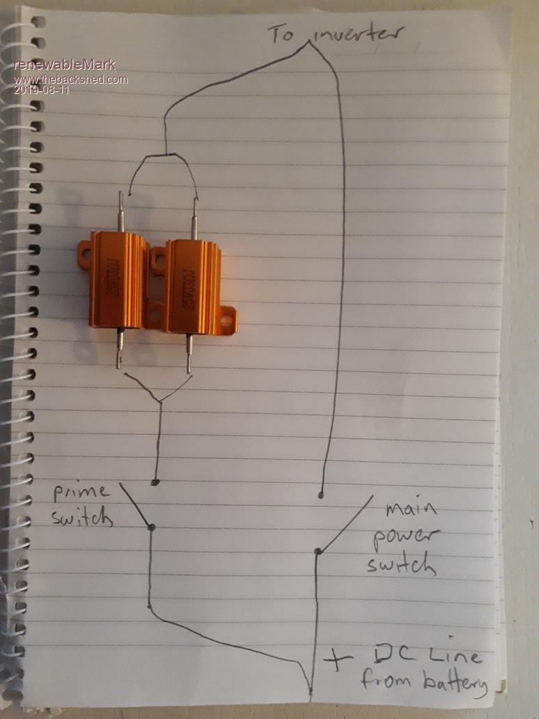 I just used the same style DC breakers for both and fitted them next to each other on the case, with a label on each one, and the start up procedure written on it. Cheers Caveman Mark Off grid eastern Melb |
||||
| Warpspeed Guru Joined: 09/08/2007 Location: AustraliaPosts: 4406 |
Ben, the problem is with the main power switch. If you connect a really large capacitor that is completely discharged to a large battery, there will be an almighty "SPLAT" and you may spot weld the contacts together. This may also damage the capacitors, as they may go open circuit with a very sudden surge of possibly many hundreds of amps. Cheers, �Tony. |
||||
| BenandAmber Guru Joined: 16/02/2019 Location: United StatesPosts: 961 |
Thanks you guys for your comments and your wisdom I will definitely add the resistors as shown above mark So is the startup procedure the same with the Nano as with esg002 So if I use a non latching switch as the prime switch How would a person hook up a LED to show when it's fully charged like mack mentioned above Would be nice if a LED would come on when it was fully charged letting you know time to turn the inverter on And is there anything else about the turn on sequence I need to know about I've heard some people saying that the esg002 chip can hang sometimes I have both Breakers and fuses on everything because I'm afraid that the arcing will cause a failure like mentioned above I will get a picture of how I have everything temporarily hooked up and uploaded here after bit be warned i am good parrot but Dumber than a box of rocks |
||||
| mackoffgrid Guru Joined: 13/03/2017 Location: AustraliaPosts: 460 |
Ben, I've been meaning to do a little schematic snippet to show this. I put the two 33R 20W resistors in series. For 48v I'd use three of the above in series. The simple way to use an LED is to have a LED in series with a 2k 1/4W resistor, this goes in parallel with the power resistor. The led will turn OFF when the Caps are fully charged. The current to charge the caps this way is in the order of 0.5 Amp so wires and switches need only be light duty. Cheers Andrew |
||||
| BenandAmber Guru Joined: 16/02/2019 Location: United StatesPosts: 961 |
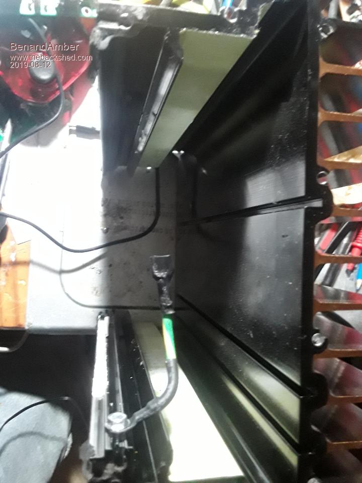
Awesome Mac do you care to do a little Doodle of the circuit you're talkin about And another question is how do you guys get these giant wires in these little lugs of Breakers and such 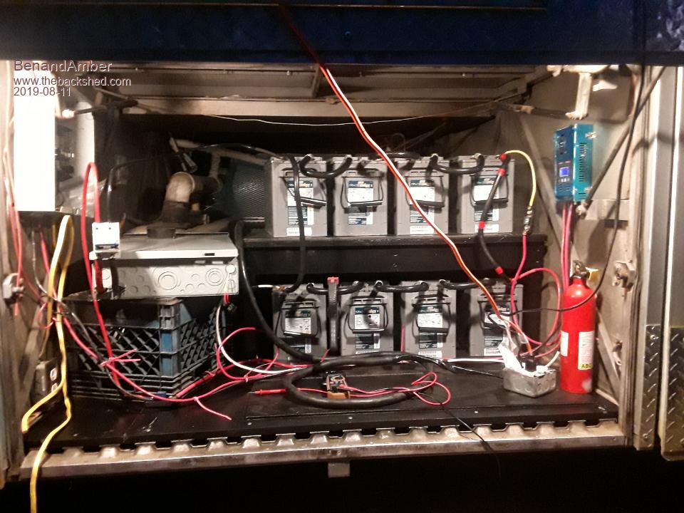 I have giant wire that's going to be going to the inverter when I hook it up permanently right now it just has a AWG 2 wire That is a hundred amp breaker that's hooked up to it I hate that you can't hardly get big wire into it they make the lugs so small It also has a hundred amp fuse you may be able to see it on the bottom right-hand side of the crate the inverter is setting on I have AWG 6 wire going to the charge controllers it also has a fuse in between it and the battery Bank The breaker box at the top left is for the input of the solar panels each breaker will be hooked up to 3 solar panels in series only have one for now 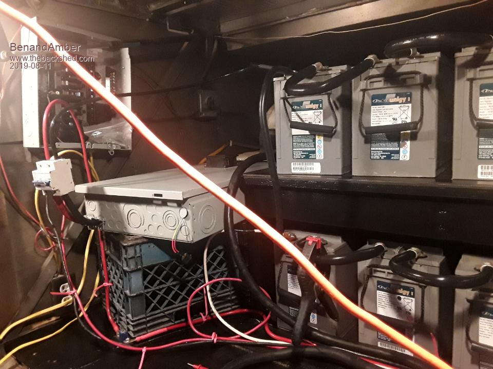 that large black wire going over the inverter has one of those giant RV 220 plugs on it it plugs right into the side of my inverter that wire will be going to the bus breaker box instead of those two receptacles when I'm all done I can unplug the inverter and plug into Shore power if I ever need to no way of messing that up both cannot be plugged in same time because they use the same plug going to the breaker box The Big sure power wire is like a giant extension cord female on one side and male on the other 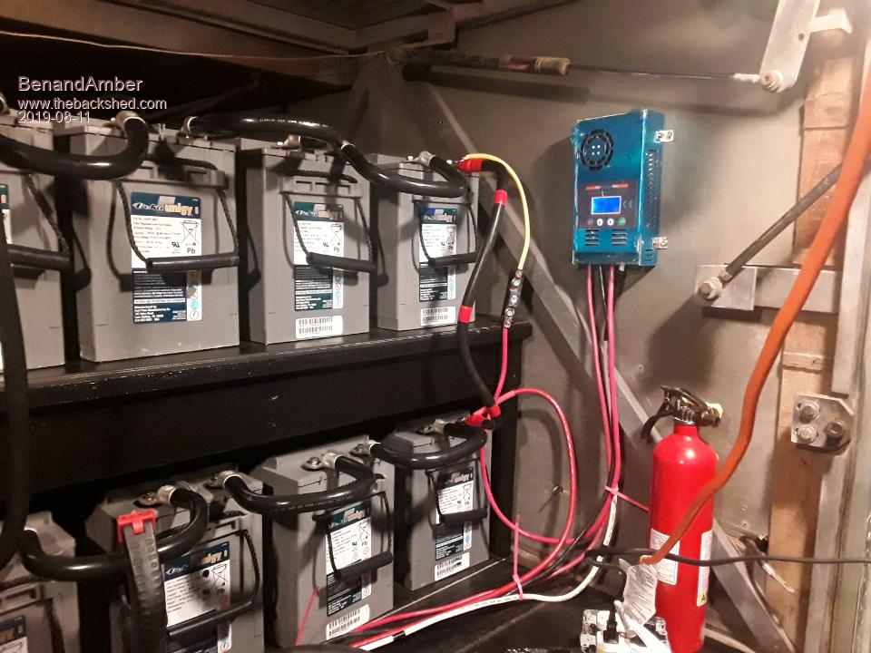 I'm still debating whether to have the charge controllers and the inverter up in the bus or keep them down in the bottom I think I'm for sure going to put the solar panel breaker box up in the bus alongside of the regular breaker box All comments and ideals are very welcome Edited 2019-08-11 12:10 by BenandAmber be warned i am good parrot but Dumber than a box of rocks |
||||
| mackoffgrid Guru Joined: 13/03/2017 Location: AustraliaPosts: 460 |
Simple charge circuit, switch and wiring see less than 1 Amp. 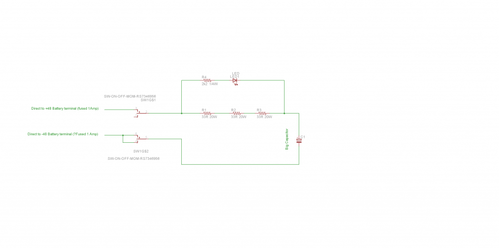 This circuit Charge and discharge, which is why you need a Bi-direction led. 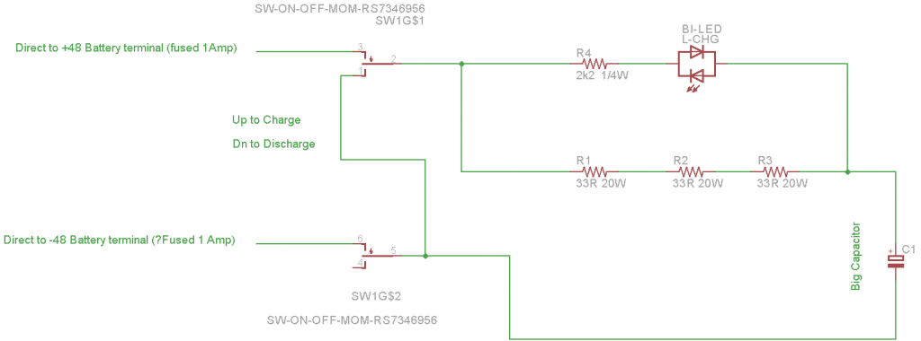 Cheers Andrew |
||||
| BenandAmber Guru Joined: 16/02/2019 Location: United StatesPosts: 961 |
You're awesome thanks for the help for me and everyone else needs extra help 2 get it the more I look at it the more I like it I think I'll build this on a little circuit board and add it to all of my inverters So simple but so elegant Is there a type of switch that stays engaged as long as power is running through it and then disengages when no power? Thanks for the help Edited 2019-08-11 13:25 by BenandAmber be warned i am good parrot but Dumber than a box of rocks |
||||
| mackoffgrid Guru Joined: 13/03/2017 Location: AustraliaPosts: 460 |
That switch is from RS-spares, the part number is on the schematic. I don't know if RS is available in the states. It's a ON-OFF-Momentary, I use the momentary for discharge. It's not intended to leave it turned on but there is little consequence if you do. Not that I can think of. Or without getting too complicated. Cheers Andrew |
||||
| BenandAmber Guru Joined: 16/02/2019 Location: United StatesPosts: 961 |
Hey Mack Mark is building a inverter for a caravan and when he was talking about building it he said he needed one that didn't have a procedure to start The circuit above is perfect for my needs but others might want a circuit that you just push the button once and it automatically charges the capacitors and then turns the inverter on And then when you hit the off button it turns it off and discharges the capacitors Sounds kind of neat for a new project but maybe too complicated to even worry about I know from watching lots of videos and reading a lot nobody likes splatting Just a thought what do you think would it be too complicated to mess with like I said the circuit above is perfect for my needs be warned i am good parrot but Dumber than a box of rocks |
||||
| renewableMark Guru Joined: 09/12/2017 Location: AustraliaPosts: 1679 |
That's a ripper circuit there Andrew, with the charge/discharge design what is the switch on the negative line for? Cheers Caveman Mark Off grid eastern Melb |
||||
| Warpspeed Guru Joined: 09/08/2007 Location: AustraliaPosts: 4406 |
Mark, its usual for a battery isolator switch to be a two pole switch to completely and safely fully isolate the battery. In other words it switches off BOTH sides of the battery. Before you can "un" isolate the battery, you need to close the contacts of a pre-charging switch on both sides. But there only needs to be a resistor fitted to one side to limit the initial capacitor charging up current. Charging up only takes a very few seconds. As soon as all of the lights and digital displays on the inverter come on, you can then safely throw the big switch. Cheers, �Tony. |
||||
| renewableMark Guru Joined: 09/12/2017 Location: AustraliaPosts: 1679 |
Ahhhh I get it, that is using both side of the switch  Well guess I'll never be a rocket scientist. Cheers Caveman Mark Off grid eastern Melb |
||||
| Warpspeed Guru Joined: 09/08/2007 Location: AustraliaPosts: 4406 |
Mark, I welded up a couple of circuit breakers before I figured all this out, so you are not alone. What I do now, is push the button, and wait for the waveform on the little oscilloscope to come up, which takes several seconds. I then know that everything is working perfectly, and I can close the battery circuit breaker, without any loud bangs or surprises, hahaha. And then the main 230v ac circuit breaker on the inverter output. Cheers, �Tony. |
||||
| tinyt Guru Joined: 12/11/2017 Location: United StatesPosts: 561 |
This is un-tested. It uses the following: 1. kentfield's pcb design you posted here 2. A 60V to 15V isolated DC-DC power supply. 3. The two 33 ohms 20 watts resistor. 4. A 1kohms 1/2 watt resistor. 5. A 1 watt tbd resistor (maybe from 100 to 300 ohms). 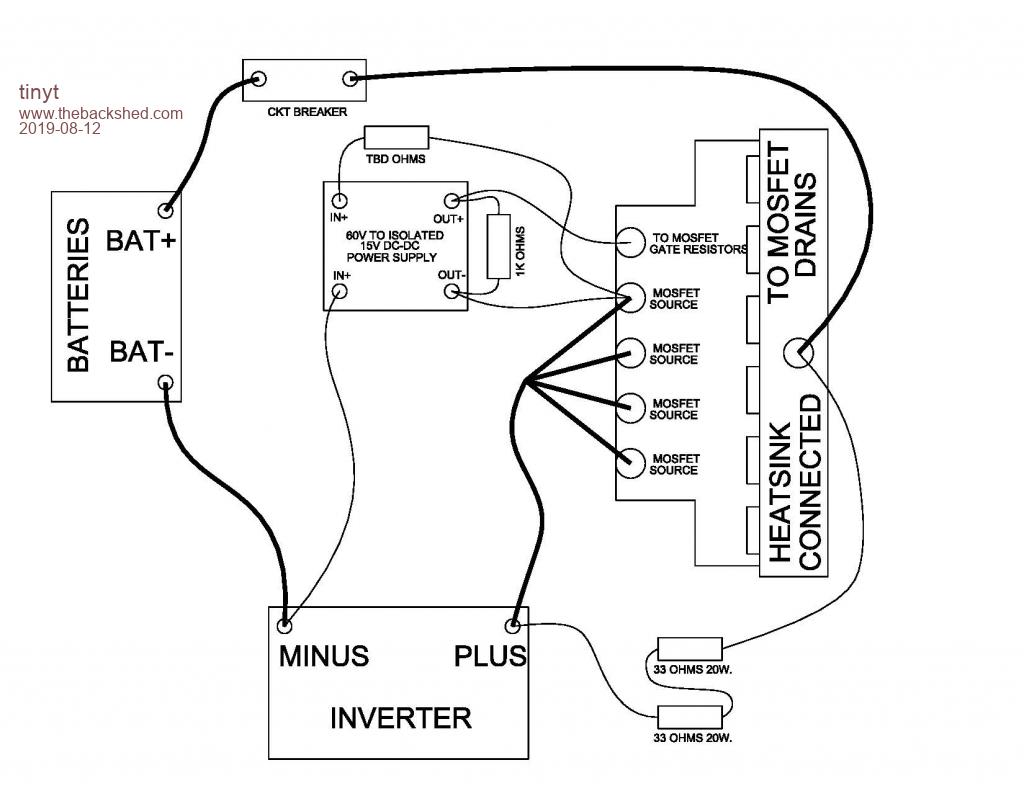 When the battery ckt breaker is turned on, the DC-DC converter waits for the inverter capacitors to reach sufficient voltage for it to build up to its 15V output. Then the Mosfets turn on, allowing full current to the inverter. The 1K resistor allows fast discharge of the 15V when the ckt breaker turns off. Of course it also depends on the discharge of the inverter capacitors. The tbd resistor creates further delay to the build up of the 15 output. Edited 2019-08-12 04:22 by tinyt |
||||
| nickskethisniks Guru Joined: 17/10/2017 Location: BelgiumPosts: 481 |
That's something that I want to do, but controlled by a uC. Maybe the second Arduino nano from the Nanoverter has some pins left to be used. It's allready meassuring all that's needed I guess. Then the uC can deside if the charging time is normal, if not give fault. Then anyone can put the inverter in to duty. The only (small) issue is the powerloss when switching an AC contactor/relay. Most of them are using +-5W. |
||||
| mackoffgrid Guru Joined: 13/03/2017 Location: AustraliaPosts: 460 |
Regarding the auto circuit, you could also use an optocoupler + R across the charge resistor, when the led turns off other circuitry could engage the inverter. etc etc. Interesting idea for a caravan or camping situation, secondly because they are usually a smaller inverter. Cheers Andrew |
||||
| BenandAmber Guru Joined: 16/02/2019 Location: United StatesPosts: 961 |
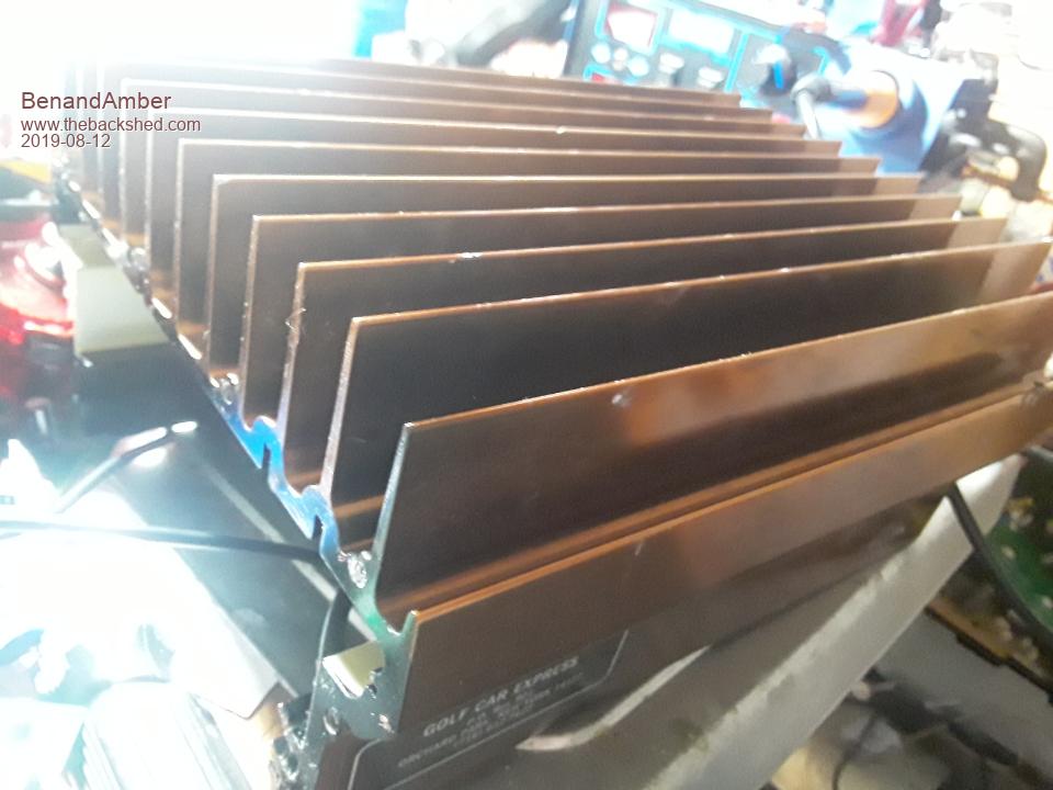  My buddy gave me a 36 volt golf cart charger that fell off the back of the truck going down the interstate all of the Transformers on the inside where broke off the board it didn't hurt the heatsink I would like to use this Heat sync on the next thing I build If it can't be used whole what are you guys cutting these aluminum heatsink with be warned i am good parrot but Dumber than a box of rocks |
||||
| renewableMark Guru Joined: 09/12/2017 Location: AustraliaPosts: 1679 |
You can just use one of these reciprocating saws with a hacksaw metal type blade. That does a pretty ugly job but it works fine and the inverter won't care. 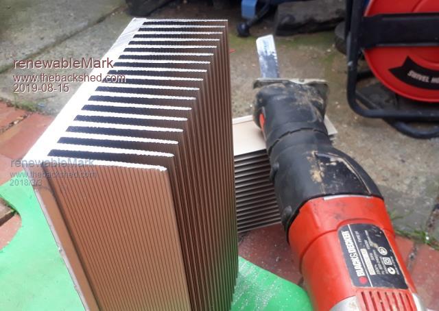 Now I use a table saw with an aluminium blade. You get nicer cuts and it's just easier if you have access to a table saw. If you do it on a table saw beware of the blizzard of tiny filings that get flown EVERYWHERE. I put on full length overalls and use a welding mask (with the dark shade flipped up). Cheers Caveman Mark Off grid eastern Melb |
||||
| Page 1 of 2 |
|||||
| The Back Shed's forum code is written, and hosted, in Australia. | © JAQ Software 2026 |
