| Author |
Message |
plover

Guru

Joined: 18/04/2013
Location: AustraliaPosts: 302 |
| Posted: 02:54pm 19 Aug 2019 |
 Copy link to clipboard Copy link to clipboard |
 Print this post |
|
It is a long shot but I may get my nose into repairing a 0-30 kV 10mA power supply.
Seems to be based around TV HV transformers.
Anybody doing any work on such items?  |
| |
davef
Guru
Joined: 14/05/2006
Location: New ZealandPosts: 499 |
| Posted: 07:34pm 19 Aug 2019 |
Copy link to clipboard |
Print this post |
|
Not for about 30 years! The tripler, the switching transistor, a high-voltage cap and then lastly the transformer.
Good luck! |
| |
Warpspeed
Guru
Joined: 09/08/2007
Location: AustraliaPosts: 4406 |
| Posted: 09:19pm 19 Aug 2019 |
Copy link to clipboard |
Print this post |
|
That is a mighty big supply, unusually powerful for that high a voltage.
Three hundred watts of dc at 30Kv is pretty serious stuff.
I have a Danbridge JP12A non destructive insulation tester here, fully adjustable from 0 to 12Kv but its just a baby compared to yours.
It uses a black and white TV type flyback supply, but without any tripler.
Its all transistors and pretty old, but still working perfectly and is sometimes very useful.
Cheers, ĀTony. |
| |
plover
Guru
Joined: 18/04/2013
Location: AustraliaPosts: 302 |
| Posted: 01:56am 20 Aug 2019 |
Copy link to clipboard |
Print this post |
|
Theory is easy enough but I find in practice there is always something that is not showing in the schematics. My lack of experience have me a bit hesitant.
I will head your warnings. |
| |
plover
Guru
Joined: 18/04/2013
Location: AustraliaPosts: 302 |
| Posted: 05:55am 23 Aug 2019 |
Copy link to clipboard |
Print this post |
|
Here is a sketch overview of one method which I am favouring at the moment if I can get it designed.
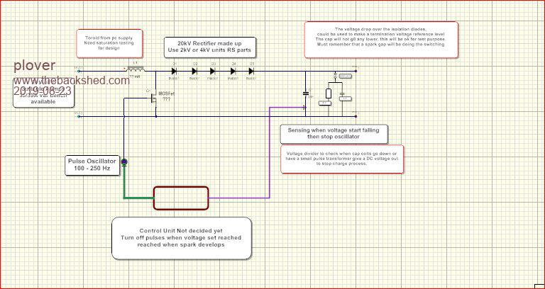
In a low voltage world I think it might work. However increasing voltage brings quite unknown problems to me I am sure.
The idea is to switch at a suitable variable frequency, thus charge the capacitor. When this reaches say 20 kV stop the charge current when the spark gap conducts and the let the cap discharge.
The high voltage is an attempt to get a very rapid rise time on the small capacitor C ??. Possibly my design falls over here that it will not be fast enough. Looking at the requirement will add this later.
I have found some 250 mA 4 kV diodes at RS
https://au.rs-online.com/web/p/rectifier-diodes-schottky-diodes/6298663/
Vishay 2000V 250mA, Diode, 2-Pin DO-204AL GP02-20-E3/54
Max Uf=3V, string of 10 gives approximate 30V base before power supply will deliver current during the last part of the caps discharge curve, ie a pedestal. Don't know if I need it.
If I charge the coil from 24V with 60 mC how many electrons will actually make it to capacitor, will the bundle of 60 mC get there. |
| |
Warpspeed
Guru
Joined: 09/08/2007
Location: AustraliaPosts: 4406 |
| Posted: 07:55am 24 Aug 2019 |
Copy link to clipboard |
Print this post |
|
Some time ago (after Fukushima) I built myself a Geiger counter.
This required about +450v for the Russian Geiger tube I used, but I wanted it to run for at least a week on a standard 9v PP9 alkaline battery. It used a voltage boost circuit similar to yours.
What I found was that the Geiger tube used almost zero power, the biggest power loss was in actually measuring the +450v with a voltage divider for the voltage feedback.
The main boost choke in my case had 500 turns, so I added a five turn secondary to that, so that when the flyback voltage reached 450v, the secondary went up to 4.5v.
I was then able to use that as the feedback voltage to regulate the voltage on the Geiger tube.
About the highest off the shelf resistor you can buy will be about 100 Meg. And at 30Kv that is going to suck a lot of power.
Cheers, ĀTony. |
| |
plover
Guru
Joined: 18/04/2013
Location: AustraliaPosts: 302 |
| Posted: 12:12pm 24 Aug 2019 |
Copy link to clipboard |
Print this post |
|
Resistive divider I realised was not likely to be an answer for measuring. In this case I plan on pulsing until the sparkgap breaks down and then stop the pulsing until cap discharge. I thought a small pulse transformer might be ideal here in the cap leg.
Any idea what frequency you are running at? |
| |
Warpspeed
Guru
Joined: 09/08/2007
Location: AustraliaPosts: 4406 |
| Posted: 10:32pm 24 Aug 2019 |
Copy link to clipboard |
Print this post |
|
I have the schematic here, but nothing on it about the frequency or the flyback inductor inductance. This all goes back at least ten years, probably a lot longer and I cannot now remember.
Anyhow, if you place a secondary winding on your flyback inductor, the volts per turn will be the same in both windings during flyback. So you have two diodes and two capacitors being charged simultaneously.
The voltages on the two capacitors will reflect pretty exactly the turns ratio on the two windings. One can be 30Kv the other for example 15v.
The clever thing about this is that you arrange to have a voltage divider on the 15v capacitor to bleed off some of the voltage between flyback pulses. If you load up the 30Kv side and the voltage there falls, the voltage on the 15v side will also fall.
Every time the inductor discharges, both capacitors will be charged up to the same relative voltage, and will track each other.
This can all run with very little power loss. In my case, to get a PP9 battery to last a week I had to keep total current consumption below 1mA. 9mW of power is not a lot to play with.
I only needed +450v, but the same idea will work just as well at 30Kv.
Cheers, ĀTony. |
| |
