Notice. New forum software under development. It's going to miss a few functions and look a bit ugly for a while, but I'm working on it full time now as the old forum was too unstable. Couple days, all good. If you notice any issues, please contact me.
piercy007 Newbie Joined: 27/06/2008 Location: United KingdomPosts: 28
Posted: 02:18pm 18 Jul 2008
Copy link to clipboard
Print this post
Afternoon All
I have been lurking for some time just watching other postings (as they seemed to answer moxt of my questions anyway) but need bit of advice really.
I am in the process of building a Wind Generator using information advice from both this and a whole host of other sites. I plan to create a full home grown version but for a Mk1 I have used an old solenoid from a set of spot lights. This is cast in resin and mounted waiting for some wings to get going
I have tested the output by hand and got a fair few Watts (AC) showing on my volt meter. But when I connect it to the bridge rectifier nothing shows up at all
I have checked the rectifier (it is also a home brew) but it seems to be wired up fine (both outputs from genny going to ac connectors then DC output connected to + and - terminals)
any ideas anybody ? I am missing something simple
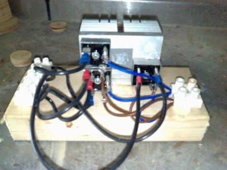
Picture below of the rectifier
My middle name is luck mind you my first is bad!
Gill Senior Member Joined: 11/11/2006 Location: AustraliaPosts: 669
Posted: 03:07pm 18 Jul 2008
Copy link to clipboard
Print this post
G'day percy007,
Welcome to the forum. It's good to see new ideas being tried. I have no idea how you go about using spotlight solenoids to generate power. Do they form the stator?
Regarding the lack of DC, as you have verified you are getting AC power from the generator, the prime contender for lack of DC must be the rectifier. Looking at the photo, to all bridges I see the black (AC?) wires going to adjacent terminals whereas they should be going to diagonally opposite terminals. Likewise the DC wires (blue and brown?) are from adjacent terminals instead of diagonally opposite ones.
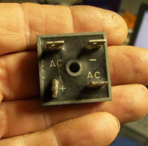
The pic below shows the terminals clearly marked. Note the lug orientation. They are the same for all these types, so making it easier to locate appropriate pins when the markings are gone.
Easy enough to change the spade connectors. How does that sound? Edited by Gill 2008-07-20was working fine... til the smoke got out.
Cheers Gill _Cairns, FNQ
piercy007 Newbie Joined: 27/06/2008 Location: United KingdomPosts: 28
Posted: 03:15pm 18 Jul 2008
Copy link to clipboard
Print this post
Cheers for the quick reply.
I had identified this already (old photo) and have changed them around - still no luck though.
As for the light I justed stripped it down and found the soleoid in the centre. I was just going to strip the wire off to use elsewhere then decided to use it direct. So basically it is a steel stator with loads of winds on it, over which I pass 10 magnets and generate some power (quick and dirty to as a first attempt).My middle name is luck mind you my first is bad!
CraziestOzzy Senior Member Joined: 11/07/2008 Location: AustraliaPosts: 152
Posted: 04:03am 19 Jul 2008
Copy link to clipboard
Print this post
I would check for continuity of current with those groups of rectifiers. Start from one end and work your way around, following the theoretical (A/C in to out and DC in to out) input to output. If in doubt, round up four schottky diodes (for one rectifier) and make your own rectifiers and see what happens. Make sure the rectifiers you setup are rated for the current you have available and all should be fine.Edited by CraziestOzzy 2008-07-20http://cr4.globalspec.com/member?u=25757
http://www.instructables.com/member/OzzyRoo/
Robb Senior Member Joined: 01/08/2007 Location: AustraliaPosts: 221
Posted: 06:35am 20 Jul 2008
Copy link to clipboard
Print this post
How many wires come out of your solenoid?
Whats the AC voltage you get?
piercy007 Newbie Joined: 27/06/2008 Location: United KingdomPosts: 28
Posted: 06:46pm 20 Jul 2008
Copy link to clipboard
Print this post
There are 2 cables coming from the solenoid and the AC varies on spedd bt around 14/15v in a normal breaze.
My middle name is luck mind you my first is bad!
Robb Senior Member Joined: 01/08/2007 Location: AustraliaPosts: 221
Posted: 02:42am 21 Jul 2008
Copy link to clipboard
Print this post
Then you only need one bridge rectifier not 3 as showen in your picture.
Conect one solenoid wires to each of the two~ or AC terminals as showen in Gills picture and you DC comes out of the + - terminals.Edited by Robb 2008-07-22
piercy007 Newbie Joined: 27/06/2008 Location: United KingdomPosts: 28
Posted: 08:45am 21 Jul 2008
Copy link to clipboard
Print this post
Hi
I had built it for a 3 phase project. I have only connected one of the rectifiers up as suggested but still no luck - this is very strange.
Never mind this gives me the incentive now to get the full 3 phase build up and running
My middle name is luck mind you my first is bad!
Robb Senior Member Joined: 01/08/2007 Location: AustraliaPosts: 221
Posted: 04:58am 22 Jul 2008
Copy link to clipboard
Print this post
Has the mill got enough AC current to light a car headlamp?
Just wonder if you'v shorted some diodes wile experimenting.
No real point moveing on to 3 phase till you'v got your head around this one.
oztules Guru Joined: 26/07/2007 Location: AustraliaPosts: 1686
Posted: 01:06am 25 Jul 2008
Copy link to clipboard
Print this post
Piercy007
If you have 15v, you should be seeing something out of it.
If you haven't got it going yet, perhaps draw a circuit or line diagram of what you have wired up.
There must be an explanation lurking within this somewhere.
........oztulesVillage idiot...or... just another hack out of his depth
piercy007 Newbie Joined: 27/06/2008 Location: United KingdomPosts: 28
Posted: 07:36am 25 Jul 2008
Copy link to clipboard
Print this post
Hi
I have been reviewing this and it may be the case that consistant power is not being generated due to the poor design and build . The Genny is only a prototype and I have now started on the second one.
I may be back soon if I have any problems with this one as it will be a 3 phase version (still not convinced myself of the circuit going into the bridge rectifier) but that will not be until some time later
Cheers for all the support - this is a very friendly and helpful forum. My middle name is luck mind you my first is bad!


 showing on my volt meter. But when I connect it to the bridge rectifier nothing shows up at all


 . The Genny is only a prototype and I have now started on the second one.
