
|
|
Forum Index : Electronics : Solar Hot Water Inverter - Batteries not included
| Author | Message | ||||
mackoffgrid Guru Joined: 13/03/2017 Location: AustraliaPosts: 460 |
As my bush block is vacant most of the time (atm) I turn the inverters and batteries, etc off. Now this will be changing but... as my first change, I want to be able to pre-heat my hot water tank. I decided I wanted to build a simple inverter to work directly from the Solar Array without the batteries connected. My array is Voc = ~40v and Vpp = ~ 30V. I'm using the same Driver Pcb and MosFet Pcb as in 26.5V WarpInverter, except they are the more recent revision as used by Mark in Mark's stock standard Warpverter but with the extra twist that I made a stm32 micro board of the same dimension as the driver PCB plug directly on top of it. As its only hot water, I can keep the hardware real simple; I'm just creating a PWM square wave at 50Hz. My PWM rate is literally 2 x the frequency I choose (100Hz), at this stage is 50Hz. To keep the project simple I'm also limiting the power to about 1000Watts. I'll use a Aerosharp 1.5kW Toroid, no choke, 1 or 2 10,000uF caps - simple. Well there are some smarts in the software. It is controlled by a simple PI algorithm and a MPPT algorithm to find Vpp. These are the Boards I'm using. 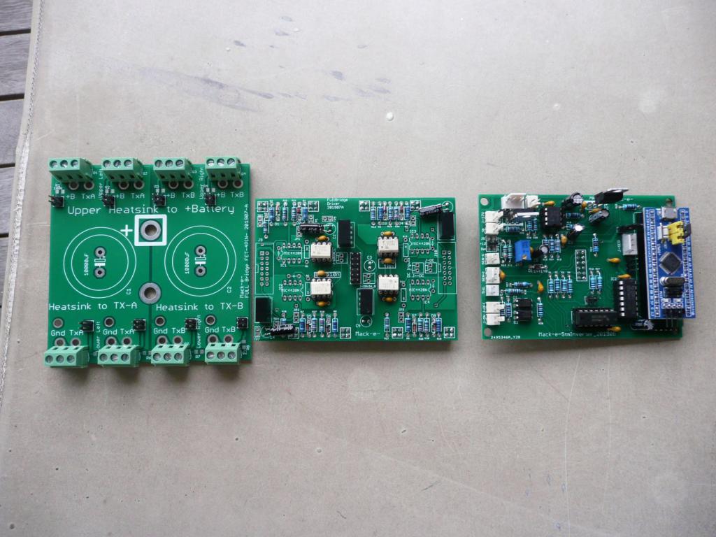 Driver Board plugged onto the Mosfet PCB. 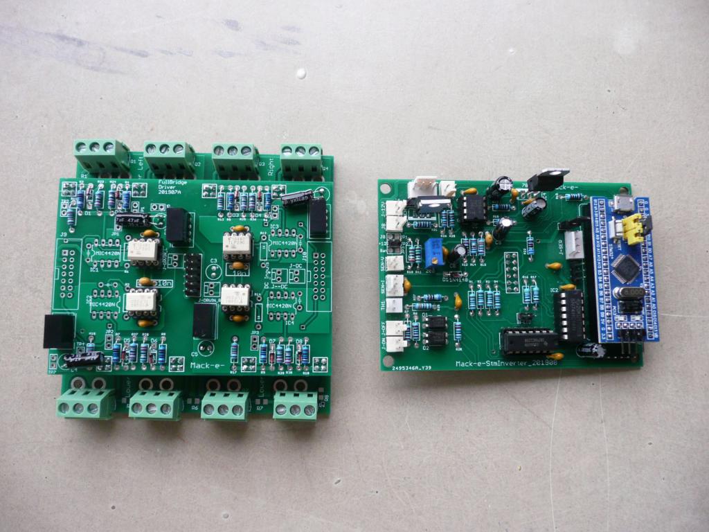 Showing the underside of the STM32 micro board - how it plugs onto the driver board. 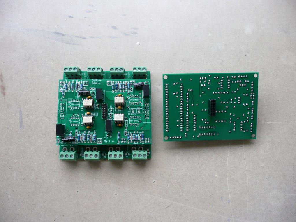 All plugged in. 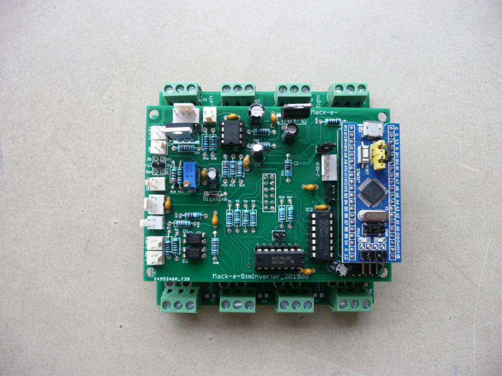 STM32 controller The STM32 board was designed to be able to work this combination of boards as a full SPWM inverter should I want to. To add power just add more Mosfet boards as can be seen with Marks warpverter project. It just so happens with this project that a square wave output is all that is needed. The controller has all the usual features, battery voltage, Battery Current, Thermistor, Fan control, ON - OFF, Bi-LED, additional analogue inputs available on headers. 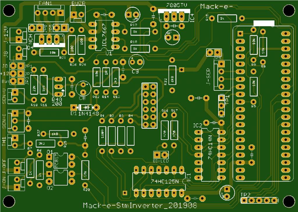 Operation I'll need a high volt LM2596, diode isolated with a decent cap to provide 12V to the STM32 controller, the pcb feeds this to driver boards which have their own isolated 12-15V power supplies. When commanded on by the remote control, it will remain off until a Voc has reached some threshold like 35Volts then have a shutdown threshold somewhere around 20V I guess. When clouds come over and interrupt the procedure it'll just wait untill conditions are safe to start up again. Cheers Andrew |
||||
| Warpspeed Guru Joined: 09/08/2007 Location: AustraliaPosts: 4406 |
I did some tests a few months back with a panel with Pmax rated at 32v. I found power fell by roughly 10% at 26v and 36v. If rated Pmax is 30v, then my guess would be 24v and 34v. Power falls off much more steeply at the high voltage end. Very nice Andrew, really like the modularity. Cheers, �Tony. |
||||
| mackoffgrid Guru Joined: 13/03/2017 Location: AustraliaPosts: 460 |
Thanks Tony A 10% power loss is neither here not there, I can just switch the inverter on a day earlier if I need to, the power is wasted anyway.  Doing some estimations on what primary I need, mulling still. Due to how my array is configured etc, I'm going to provide 12 CSUN-250W panels out of the array to supply the inverter. 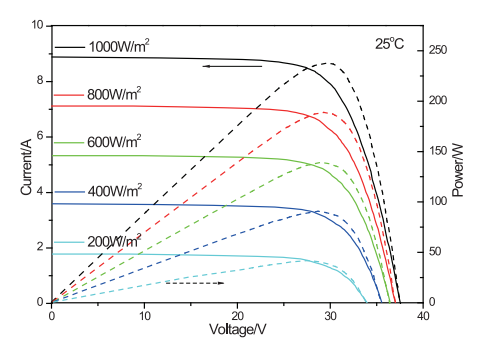 Resources - The HW element is a 1800W element. - 3000 Watts Solar at 1000W/m2 So irradiance drop to 333 W/m2 should still be able to provide my 1000 Watts I desire. If irradiance drops to where Pmax is below 100 to 200 Watts I'm happy to call it and either stop inverting or not fussed about optimisation. - It looks to me that (on the chart) Vpp @ 333 W/m2 is about 28 Volts ??? R(element) = (240^2)/1800 = 32 ohms Vrms @ 1000W = sqrt(1000*32) = 178.9 Volts My feeling for the minimum primary voltage is around the figure you're highlighting, 24 Volts. So, turns ratio = 178.9 / 24 = 7.12 I could lower input ripple current by raising the primary closer to that 28V minus some voltage drops, or I could chase the MPPT level down to 20Volts, but 24V should do I would think. Cheers Andrew |
||||
| Warpspeed Guru Joined: 09/08/2007 Location: AustraliaPosts: 4406 |
That all looks very good Andrew, should work very well. Are you planning to use square wave drive to the heating element, or sine wave PWM? Edited 2019-08-29 07:11 by Warpspeed Cheers, �Tony. |
||||
| mackoffgrid Guru Joined: 13/03/2017 Location: AustraliaPosts: 460 |
Square wave, 3 states, I'm going to set a maximum, arbitrary on-time, somewhere between 90% and 99%. �My software is set for 90% at the moment. I think 90% is too conservative , perhaps 95%. I have done the code for a sin wave SPWM as an exercise but I didn't see the need for that for a hot water element. I'm also using centre aligned PWM, or dual slope, probably not very important for a heater element. I'll be using the existing 235V secondary so the Volts / turn will be lower by 23%. I'll use ~ 8mm2 wire for the new primary that I'll wrap over the toroid as it is, leaving all existing windings intact. I intend for the inverter to run fanless, for the heck of it �  � I can modulate the output if temperature gets too high. �The control for Fan is there, I can use PWM or Bang-Bang control modes, I'm just trying to reduce hardware a little and see what can be achieved without a fan. � I can modulate the output if temperature gets too high. �The control for Fan is there, I can use PWM or Bang-Bang control modes, I'm just trying to reduce hardware a little and see what can be achieved without a fan. Cheers Andrew Edited 2019-08-29 07:20 by mackoffgrid |
||||
| Warpspeed Guru Joined: 09/08/2007 Location: AustraliaPosts: 4406 |
I was curious from the point of view of contact arc suppression, and dc input ripple current into the inverter. Three state dc will be a lot simpler software wise, potentially more efficient, and should work better anyway. Ninety percent max might be safer. The ten percent off time will allow any formed plasma arc to cease and cool down before the next half cycle begins. A slightly higher transformer secondary voltage can easily more than make up for the lost ten percent in duty cycle. Edited 2019-08-29 08:30 by Warpspeed Cheers, �Tony. |
||||
| mackoffgrid Guru Joined: 13/03/2017 Location: AustraliaPosts: 460 |
I didn't think of needing the arc plasma to cool down, good idea. Adjusting the transformer will be easy. Minimum Off time, base frequency (currently 50Hz) is all just a parameter change. |
||||
| mackoffgrid Guru Joined: 13/03/2017 Location: AustraliaPosts: 460 |
Mechanics So far. I'm joining in by using terminal blocks to hold the Mosfets. I'm using the 50x50x6 Al angle as the heatsink and as electrical connection to +Solar and transformer connection. And I'm using the negative pad of Mark's screw capacitor to connect to a little -Solar buss. I'll use 1 or 2 10,000uF caps held by a 3D printed housing and wired connection to the + and - Solar buss's. The transformer will be mounted in its original Aerosharp box underneath the Solar panels and the Inverter electronics will go into an existing electrical box which is also underneath the solar panels. Security cable (10m run) will used to convey On-Off control and data logging to the Automation equipment. Cheers Andrew |
||||
renewableMark Guru Joined: 09/12/2017 Location: AustraliaPosts: 1678 |
So with that third little board it turns into a SPWM inverter, wow that's impressive. Such a compact little unit, I think this will catch on. Cheers Caveman Mark Off grid eastern Melb |
||||
| renewableMark Guru Joined: 09/12/2017 Location: AustraliaPosts: 1678 |
Hey Andrew, I'm just having a better look at this. So basically you have this running from solar feeding a HWS. But the top board is not only a SPWM control board it also is an MPP solar tracker. is that right? Could you then run it with solar input as you have done here, but use the output to charge batteries? Cheers Caveman Mark Off grid eastern Melb |
||||
| mackoffgrid Guru Joined: 13/03/2017 Location: AustraliaPosts: 460 |
Mark, you are correct about MPPT. I'm sure it could be configured to charge batteries. There is probably better gear out there, at least for 48v batteries. At Higher voltages the situation changes, one which I'm contemplating at the moment. Cheers Andrew |
||||
| renewableMark Guru Joined: 09/12/2017 Location: AustraliaPosts: 1678 |
Well there aren't any DIY MPPT chargers out there. So there is nothing to compare it to. PWM Mad board works fine. For those with small roofs an MPPT will squeeze just that little bit extra out of their system. Something to think about. Cheers Caveman Mark Off grid eastern Melb |
||||
| mackoffgrid Guru Joined: 13/03/2017 Location: AustraliaPosts: 460 |
Mad's board is all about pwm'ing the input of a GTI inverter isn't it? Mike from NZ has a few designs for MPPT but I don't know how finished they are. If I remember your battery is big Lead Acid so they wouldn't mind a bit of ripple. You could grab my boards and wind a transformer such that the minimum solar panel voltage that is worth while would still charge the battery, after it's rectified and feed through some sort of choke. I guess you'd be able to charge them at 2 to 3 kW using an aerosharp core. One or two of those Aerosharp chokes might do the job. I don't know what the ripple would be but I reckon the LA batteries wouldn't mind and might even be good for them I'm going all lithium and I have a suspicion they don't like ripple current???? Cheers Andrew |
||||
| renewableMark Guru Joined: 09/12/2017 Location: AustraliaPosts: 1678 |
Mad's board will throttle a GTI that is backfeeding (bottom fets), it also is a PWM panel controller (top fets). A good solid board, but a DIY mppt would be awesome. Maybe your stm mppt algorithm could be used in the Mad controller?? Cheers Caveman Mark Off grid eastern Melb |
||||
| mackoffgrid Guru Joined: 13/03/2017 Location: AustraliaPosts: 460 |
I haven't followed Mad's GTI controller very much but I'd suggest MPPT is being used by the GTI inverter - Mad's GTI is merely throttling back the power because the batteries need the charge backed off. If the weather is grey then I presume MAd's GTI controller would be at 100% and the GTI inverter would use it's MPPT algorithm to maximise Power. As I said previously a simple bulk charger charger would be very similar to the hot water inverter. Add a big rectifier (can be made more efficient with mosfet rectification), capacitor, choke - done. This would be good if the panel voltage is quite different to the battery voltage, or charging from 240v source like a genie. But this is using the big steel cores at low frequency - the Mack Truck approach. If you want the Porsche approach then look towards the work that Mike from NZ is doing. Mark, I'll keep your thoughts in mind; I'm starting to gather more gear so I can experiment while I'm in Brisbane, Looking for hot water systems and some more batteries. Cheers Andrew |
||||
| The Back Shed's forum code is written, and hosted, in Australia. | © JAQ Software 2025 |
