
|
|
Forum Index : Electronics : 'ON' timer with zero standby current....
| Author | Message | ||||
Grogster Admin Group Joined: 31/12/2012 Location: New ZealandPosts: 9985 |
Hi folks.  I need a simple way to hold a wireless transmitter keyed on for a couple of seconds, rather then just the short press often made by the Human. The first concept I came up with, was a simple transistor buffer with a cap on the base like this: 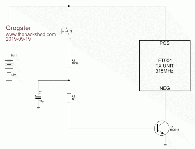 This DOES work fine, to keep the transmitter on for about one second or so, even with a very quick press of S1, but the problem is that as C1 discharges via T1, the transmitter sees a dropping voltage rather then the voltage just being cut off sharply. The next thing I am thinking of is the good old-faithful 555 timer IC setup as a one-shot, but all the circuits I have found for that, involve you having to power the 555, and then trigger it. I need a circuit that sucks no current at all, till it is tripped by the push-button, which then holds the transmitter on for 1-2 seconds, then the entire circuit powers off. The entire circuit runs of an A23 12v battery, so there really needs to be zero standby current, so as not to flatten the battery prematurely. Anyone got any other ideas? I will keep researching the 555 idea..... Smoke makes things work. When the smoke gets out, it stops! |
||||
bigmik Guru Joined: 20/06/2011 Location: AustraliaPosts: 2981 |
Hi Grogs, Why not drive a Relay with the transistor? Kind Regards, Mick Mick's uMite Stuff can be found >>> HERE (Kindly hosted by Dontronics) <<< |
||||
TassyJim Guru Joined: 07/08/2011 Location: AustraliaPosts: 6543 |
Try a FET instead of the transistor. Jim VK7JH MMedit |
||||
| Grogster Admin Group Joined: 31/12/2012 Location: New ZealandPosts: 9985 |
@ Mick: Yes, that is an option I had not considered. The current sucked from the battery is only going to be 2-seconds or so, so the relay coil current should be very small. I am thinking one of those SPST DIL reed-relay things, as they have a very small coil current. @ Jim: Would not a FET have the same issue? IE: the gate current is practically nothing, so C1 could be very small, but as the FET slowly turns off as C1 discharges, would you not have the same issue in that the voltage seen by the TX module would slowly decay from 12v rather then switching off quickly? I have plenty of those DIL reed-relays, so I might just use one of those and do as Mick says. That would ensure a quick turn-off of the TX module. Thanks to both of you for your comments. Smoke makes things work. When the smoke gets out, it stops! |
||||
| Pete Locke Senior Member Joined: 26/06/2013 Location: New ZealandPosts: 184 |
You might even find the hysteresis of the relay good enough to do away with the transistor. Just bung a cap across the relay coil and throw power at it through your switch. On duration depends on the value of the cap... Cheers Pete'. |
||||
| Grogster Admin Group Joined: 31/12/2012 Location: New ZealandPosts: 9985 |
Thanks, yes, I will breadboard this idea before I get too carried away.  Good to see another Kiwi here. Smoke makes things work. When the smoke gets out, it stops! |
||||
| Solar Mike Guru Joined: 08/02/2015 Location: New ZealandPosts: 1228 |
Add another transistor to create a snap action switch see this short article here 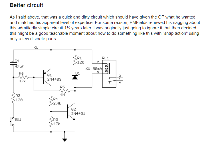 Cheers Mike |
||||
| CaptainBoing Guru Joined: 07/09/2016 Location: United KingdomPosts: 2171 |
bit of a long shot but, consider a "slugged" relay. These have a large metallic mass that inhibits the collapse of the magnetic field and modifies the activation and release of the relay �often for delayed release. Very often found in old telecoms stuff. If you can find one that is slugged for long enough duration and is happy at 12V, you won't need anything else but your push-button switch. This example �probably not what you are after but they are around. Maybe pick up some pointers here �on how to slug your own relay? might be fun to experiment with Edited 2019-09-20 01:56 by CaptainBoing |
||||
| Warpspeed Guru Joined: 09/08/2007 Location: AustraliaPosts: 4406 |
How about a cmos buffer with a Schmidt trigger input such as a CD40106 ? Less than 8uA standby current, and very abrupt output switching. It won't have enough output grunt to power your transmitter directly, but it could be used to switch a suitably large mosfet on and off. Cheers, �Tony. |
||||
| Grogster Admin Group Joined: 31/12/2012 Location: New ZealandPosts: 9985 |
@ Mike: This looks good. I will breadboard that and see what happens. Thanks. Thanks also to Captain and Tony. I will look into those ideas too. Smoke makes things work. When the smoke gets out, it stops! |
||||
| Grogster Admin Group Joined: 31/12/2012 Location: New ZealandPosts: 9985 |
This one does not work as expected. �Current consumption is about 20mA at all times, and no matter what I do with the cap value, once triggered, the relay stays on permanently. �It never switches off. �I can only reset it by pulling the power. EDIT: I trip the circuit with the button, and once the button is released, the relay NEVER drops out - even with the likes of 100n as the cap. I can pull out the cap and the relay stays on till I pull out the power. The research continues. Edited 2019-09-20 18:33 by Grogster Smoke makes things work. When the smoke gets out, it stops! |
||||
| Solar Mike Guru Joined: 08/02/2015 Location: New ZealandPosts: 1228 |
I have never tried that cct, so bread boarded it and it does as you say, never drops out. Place a 100k resistor between Q1 base and emitter to draw off some of the base current and increase R5 to 6M8, R4 to 10k and it works as described at 12 volts Cheers Mike |
||||
| Grogster Admin Group Joined: 31/12/2012 Location: New ZealandPosts: 9985 |
Excellent!  Thank you very much, this is now absolutely perfect!  I will use this circuit. Current consumption with the button o/c(open-circuit) is zero - wonderful. Current consumption when I push the button is about 16mA and that includes the relay coil. As I only need the cct(circuit) to stay 'ON' for about 1-2 seconds, this is acceptable. I will probably swap the DIL relay for a reed-relay to drop that current down even more, or perhaps just put the TX where the relay is now. Smoke makes things work. When the smoke gets out, it stops! |
||||
| robert.rozee Guru Joined: 31/12/2012 Location: New ZealandPosts: 2541 |
the following may also work, although is a little more complicated: .gif) (adapted from figure 10 here: https://www.nutsvolts.com/magazine/article/555-monostable-circuits ) upon pressing the "start" button, R3/C3 resets the 555, starting the timing period. during the timing period RLA is activated, bridging the "start" button. the timing period is set by RV1+R1 and C1, ranging between 1 and 10 seconds. upon completion of the timing period, power is cut to everything. i've not tested the circuit, but it all looks correct! cheers, rob :-) |
||||
| Grogster Admin Group Joined: 31/12/2012 Location: New ZealandPosts: 9985 |
Thanks for the post, Rob. I can confirm that the two-transistor arrangement now works perfectly, and if I simply replace the relay with the TX unit, and remove D1 and R1 as they are no longer needed(no back-EMF from the relay coil to worry about), then pressing SW1 results in the TX being keyed on for about 1.5 seconds with a 4u7 C1, then the entire circuit switches off. Perfect. Total current while powered and TX on is about 20mA. Smoke makes things work. When the smoke gets out, it stops! |
||||
| The Back Shed's forum code is written, and hosted, in Australia. | © JAQ Software 2026 |
