
|
|
Forum Index : Electronics : Square Transformer rewind
| Page 1 of 2 |
|||||
| Author | Message | ||||
| BenandAmber Guru Joined: 16/02/2019 Location: United StatesPosts: 961 |
Waste of time or good backup Transformer With the old wire this Transformers idle current was 0.07 None of the toroids I have are that low I am rewinding it with two parallel 12 gauge wire I think it's called two in hand 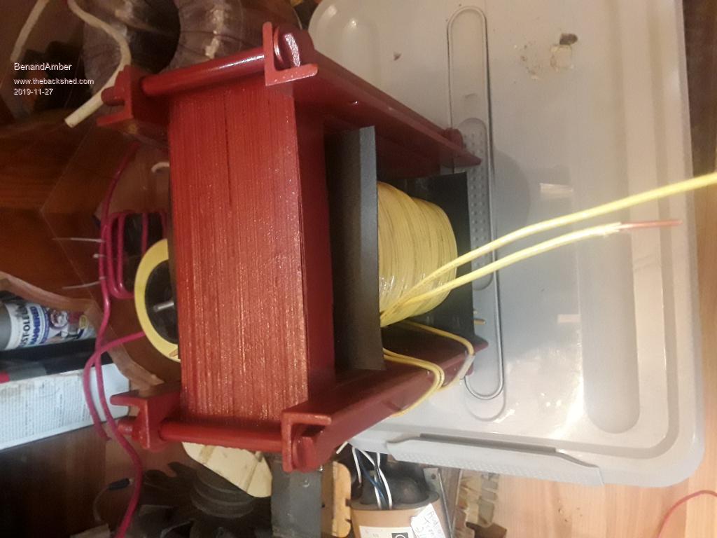 If the new Idol current is below 0.20 I'll be happy 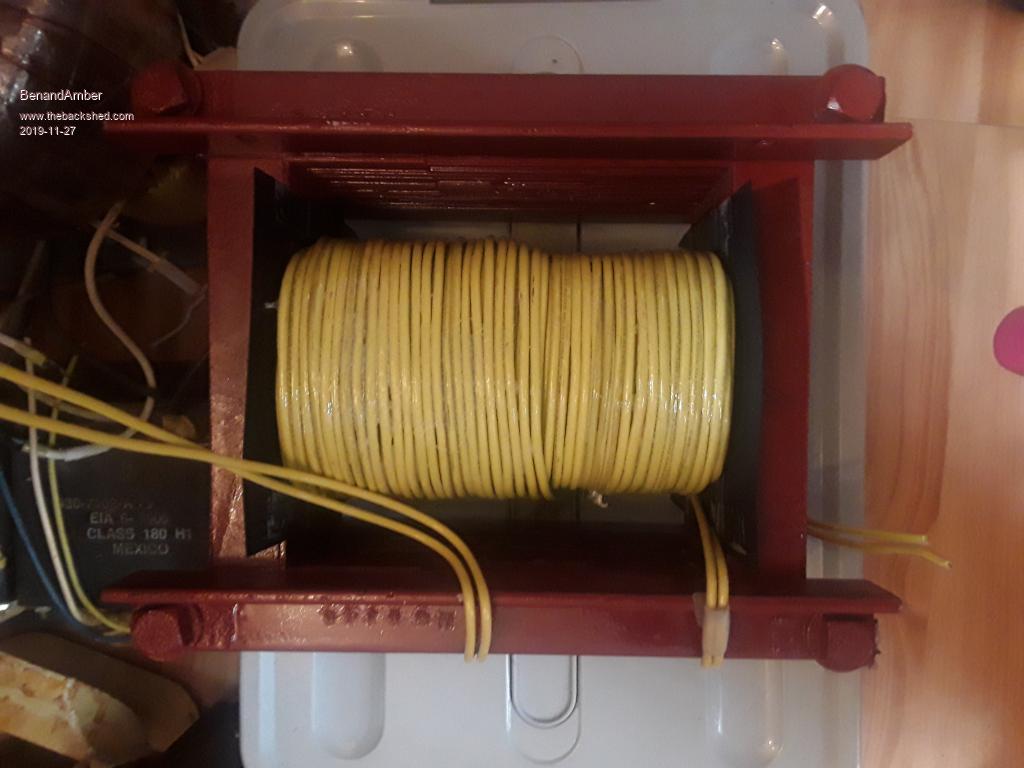 It had 90 turns of the old wire on it I'm over halfway done I am going to put just as many turns as will fit I will be leaving just enough room to squeeze in the primary I weighed it on my bathroom scale and it's a little over 40 pounds right now I am hoping for a 3000 watts continuously Warpspeed will know exactly what it will do and he will not sugarcoat it The Old Wire was in pretty rough shape 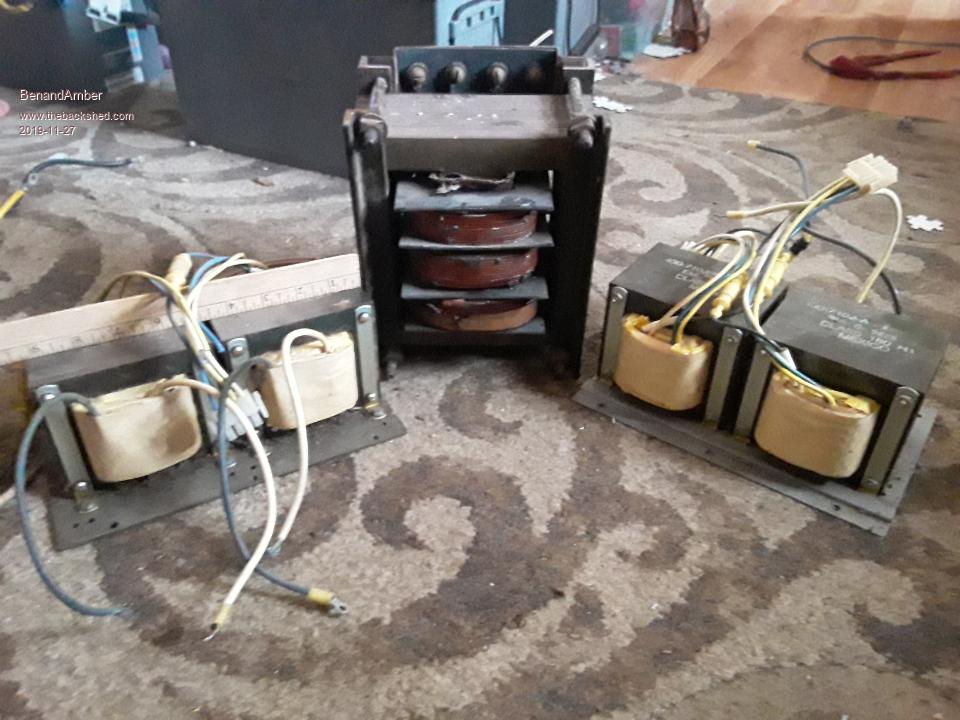 I reused this Old Wire after sprayed it with Transformer spray I epoxied it as I was putting it on a toroid I also brushed on a couple more layers after I was finished with each layer Edited 2019-11-27 05:22 by BenandAmber be warned i am good parrot but Dumber than a box of rocks |
||||
| BenandAmber Guru Joined: 16/02/2019 Location: United StatesPosts: 961 |
We finished the rewind the idle current is 0.12 Also won the bid on a toroid on eBay 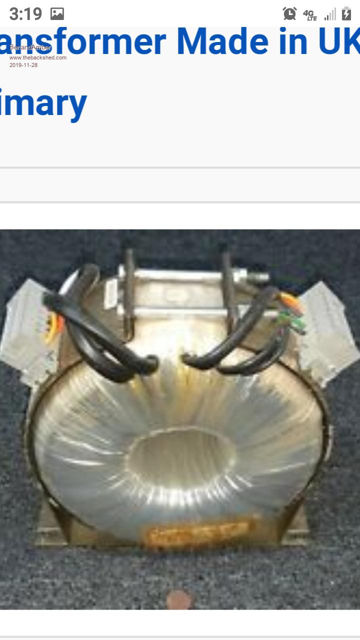 The guy didn't have any info on it he just knew it was 40 pounds be warned i am good parrot but Dumber than a box of rocks |
||||
| noneyabussiness Guru Joined: 31/07/2017 Location: AustraliaPosts: 527 |
Good job on the rewind and win , B & A. I think it works !! |
||||
| BenandAmber Guru Joined: 16/02/2019 Location: United StatesPosts: 961 |
 Transformer came sooner than expected Top layer was a 12 volt winding it had about five layers of tape on top Second layer was a 220-volt winding It also had about five layers of tape on top and underneath it the last winding has copper aluminum foil wrapped around it with some kind of ground wire I stopped at one layer of tape above that Idle current is 0.07 Seems to be a pretty nice Transformer It supposedly came out of some kind of hospital equipment be warned i am good parrot but Dumber than a box of rocks |
||||
renewableMark Guru Joined: 09/12/2017 Location: AustraliaPosts: 1679 |
Jesus Ben, how many machines do you plan to build? Cheers Caveman Mark Off grid eastern Melb |
||||
| BenandAmber Guru Joined: 16/02/2019 Location: United StatesPosts: 961 |
I saw pics of your last build last night I am so impressed with your work I just have the big one at bus and two power jacks One power jack is new unused other needs control board and Transformer All others I have gave away for free to very needy people I plan on helping anyone that I can Lots of very poor but good people in my area be warned i am good parrot but Dumber than a box of rocks |
||||
| BenandAmber Guru Joined: 16/02/2019 Location: United StatesPosts: 961 |
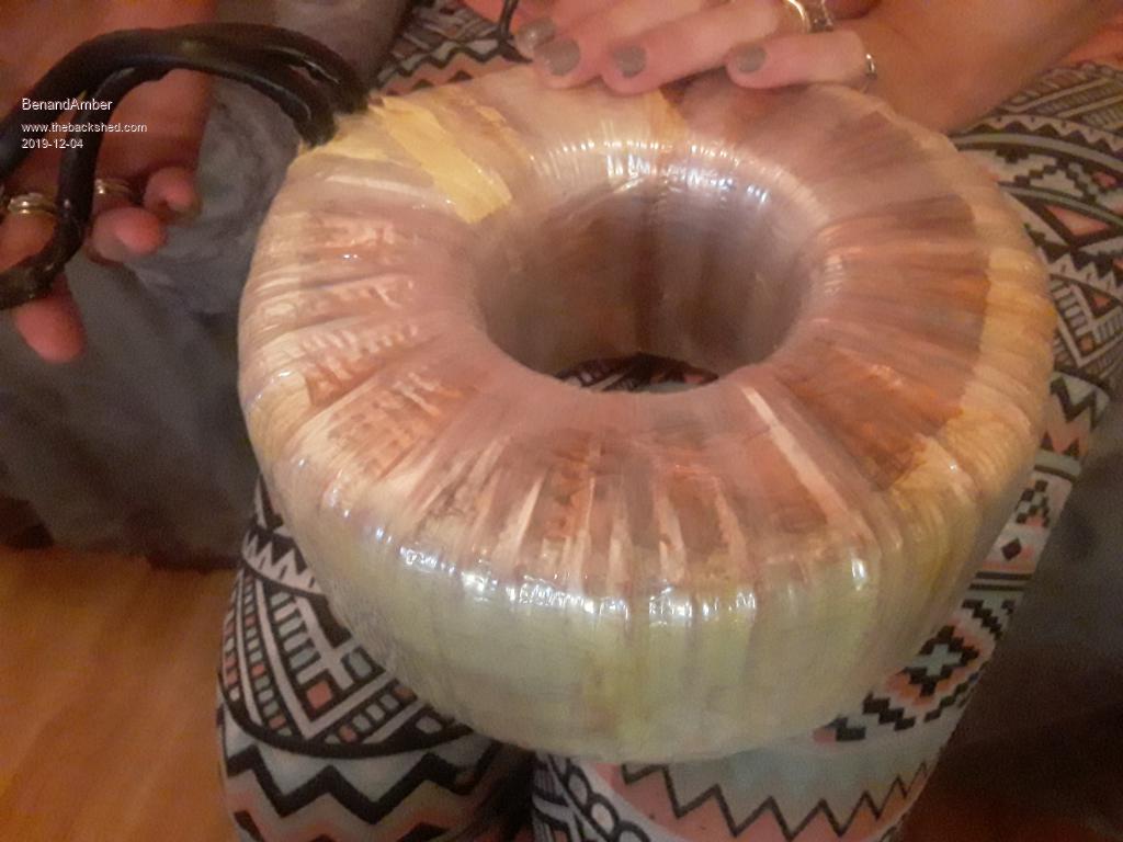
With my latest toroidal Transformer the one pictured above I would like to try to figure out a way to match the copper weight of the primary low side to the secondary high side The secondary is already wrapped on this Transformer I would like match it without having to unwind it Probably impossible but if anybody would know it would be someone on here another thing I'm trying to wrap my head around is Tesla's hairpin circuit if anyone has any information on these subjects I would greatly appreciate it Thank you for your comment on the Square Transformer rewind noneya It has a lot more wire on it since that picture was taking we filled it up as far as we possibly could still have room for the primary 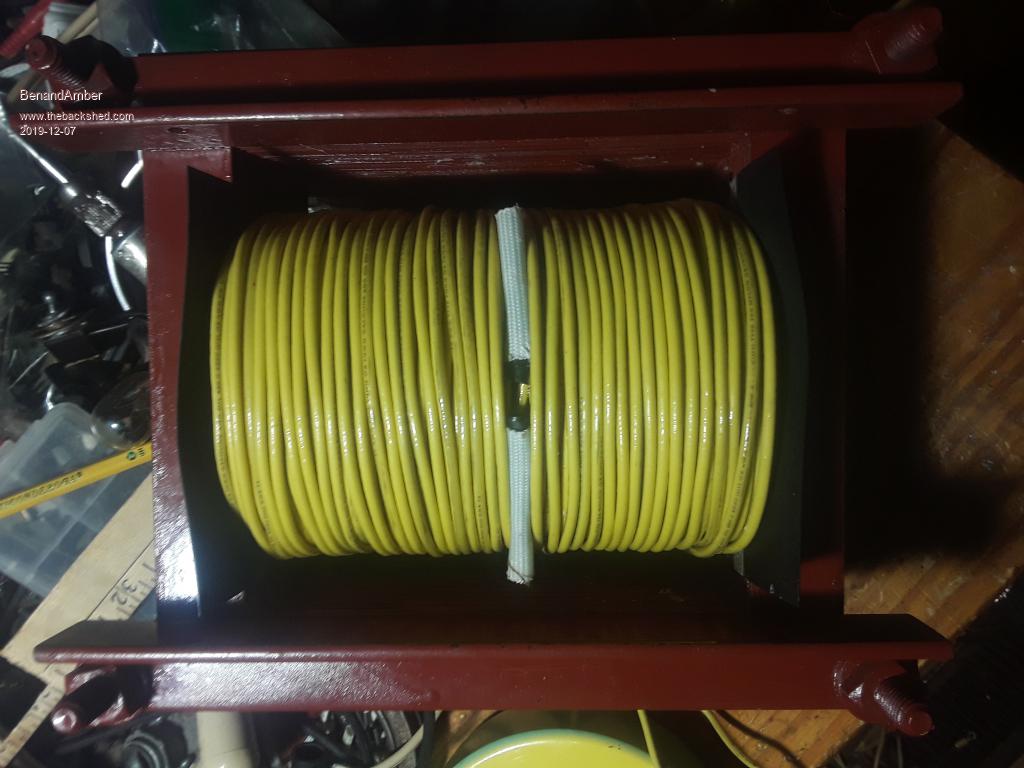 Edited 2019-12-07 12:54 by BenandAmber be warned i am good parrot but Dumber than a box of rocks |
||||
| BenandAmber Guru Joined: 16/02/2019 Location: United StatesPosts: 961 |
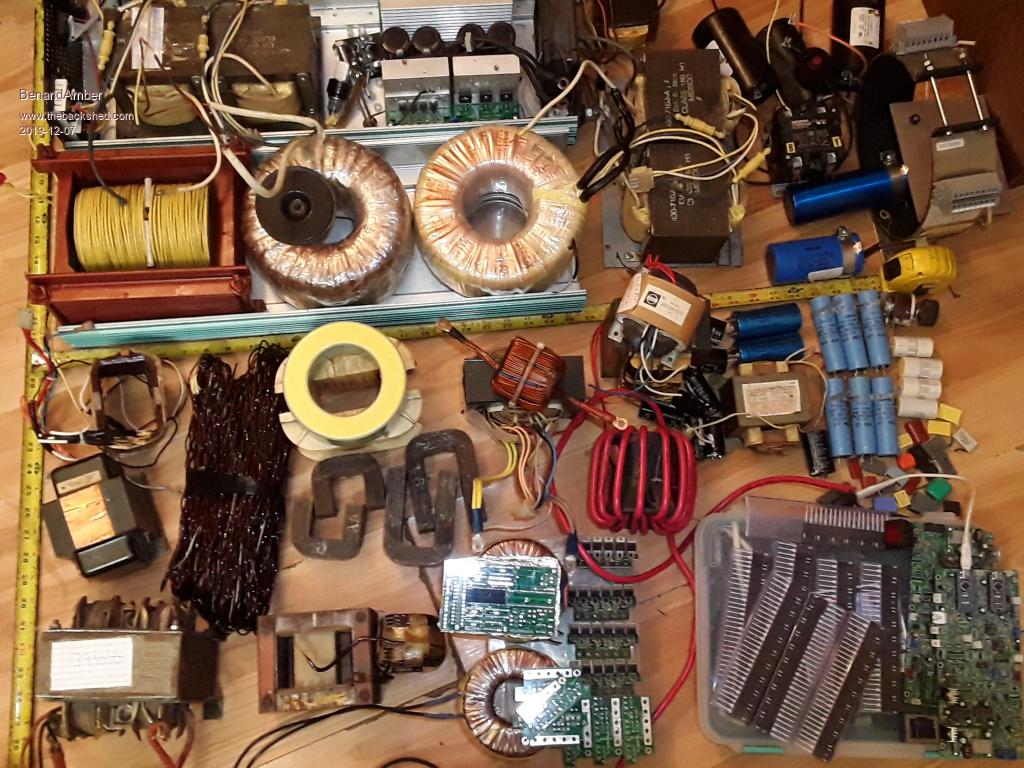 This picture May remind you of where's Waldo but there is a method to the madness or maybe not maybe it's just all Madness When cold weather came I moved my whole shop into one side of the kitchen Amber and I work on everything together and after 21 years still best friends and enjoy each other's company OK down to the fun stuff In 1/2 of the inverter case you will see 2 APC Transformers I have four of them they are identical The fella on here that has tons of capacitors in his solar set up has six of them he said that two of them will do 4000w In the top half of the inverter case you will see 3 Transformers the square one is the one that Amber and I just got finished winding few days ago I thought I read somewhere that warpspeed said The more copper the better fill a Transformer up so that's what we done It is wound for a hundred and twenty volt secondary It reads somewhere between 7 and 8 ohms across the winding when powered up by 122 volts main Supply the idle current of the Transformer is somewhere around 0.11 to 0.13 Hope we didn't put too many turns on it Any thoughts on that is appreciated Moving on the toroid in the center is the one that me and Amber unwrapped a bunch of smaller toroids and made one large one It has no primary on it yet It only has the secondary If I remember correctly it's idle current was 0.37 powered by 120 volt Mains That seemed a little high to me Each of the little toroidal Transformers it is made out of had two or three strips of silicon Steel They were not made of one continuous strip of silicon Steel So this big Transformer was made up of a lot of short strips of silicon steel To make the Transformer thicker we built two of them and stackd them on top of each other and epoxied them together We wrapped these shorts strips around thick-walled sewer pipe this allowed us to pull extremely hard to make sure they were wrapped extremely tight We also baked them in the oven and tried to match how thay are made at Factory I think the higher idle current has nothing to do with the two toroids being stacking one on top of the other I think it has something to do with being made of so many short strips Others on here will be a lot more knowledgeable than me about this subject The first toroid the wife and I made was made up of 4 or 5 of these exact same small toroid cores stacked one on top of each other It made for a very funny looking Transformer very tall but not very wide It has a low idle current it's a really awesome Transformer I build a inverter with it and gave it to my dad he is still using it I have a hunch that making a toroidal Transformer tall instead of wide makes for a lot better performing Transformer Anyone that has information on my hunch please comment Okay moving on the other toroid that is on the end is the most recent one we acquired I am very impressed with this Transformer it had several windings on it Luckily the bottom winding is the largest awg (mm) wire and is a 120 volt winding The idle currant at 122 volts was 0.07 amp It weighed approximately 40 lb before I removed all but the bottom windings As it is now it has one layer of tape and under that layer of tape it has copper foil this copper foil has a single wire coming off of it Should I take this copper foil off?? is this copper foil wire grounded to the case when you build an inverter As you can probably tell we have not yet wound the primary on it Okay moving on the yellow ferrite toroid is the exact same as the one we wound for a choke for the 10000w China board It is one giant ferrite the choke beside the yellow toroid that is already wound is made of four of the blue regular size ferrite core's You can buy these already wound off AliExpress but they are very expensive so we wound our own The one just like it on AliExpress they say it is good for 400 amps LOL There is a audio Transformer that has covered windings on each of the two legs It is made up of silicon steel but it is actually round instead of square shape There are numerous other Transformer and inductor cores in this picture We will be putting that power jack in the picture back together again pretty soon As soon as I get the time to learn how to program those two Nano boards you see in the picture If anyone has any suggestions tips or would just like to say which of these components they would use in that power jack I would like to read about it As you can see if you made it this far on this giant wall of a post I like writing long posts and I like reading your guys's long post You thought it was actually over didn't you just kidding lol there's one last thing I would like to say There is one thing in this picture that means more to me than all the others it's a little green Square and it was gave to me for free I will most definitely be using it one day hopefully not too far away The man that gave this to me is wiser than words can describe he is very generous with his time and wisdom I would like to give him a very special thanks !!! And I would like to thank all of you guys on this form for sharing your wisdom thoughts and opinions Thanks for reading and have a blessed day be warned i am good parrot but Dumber than a box of rocks |
||||
| noneyabussiness Guru Joined: 31/07/2017 Location: AustraliaPosts: 527 |
On the note of your new transformer, leave the wires on there, wrap 10 turns of any wire and attach the 120v winding to 120v.. it will give you your turns ratio, and how many turns you need for your secondary... put the numbers (voltage on 10 turns with 120v side energized) here and someone can help you with it.. good luck with your endeavors.. I think it works !! |
||||
| BenandAmber Guru Joined: 16/02/2019 Location: United StatesPosts: 961 |
The chicken scratch in these two photos is an actual Factory built Transformer This Transformer will not be used for a inverter I am using it for a example to try to gain a better understanding As you can see with my junky multimeter some of these lead combinations have zero idle current The second picture is how I interpret these leads it may be wrong I was trying to understand which of these combinations would be best for a inverter Transformer How do you know it is too little turns How do you know it is too many turns The formula 4 turns per volt I have been using has work well for me I always add 10 to 20 more turns to it I would like to understand turn ratios a little better for tweaking Transformers one way or the other The wire combinations that have zero idle current do not turn the light bulb on On the Transformers I hand wind the light bulb is always on dimly before I turn switch on 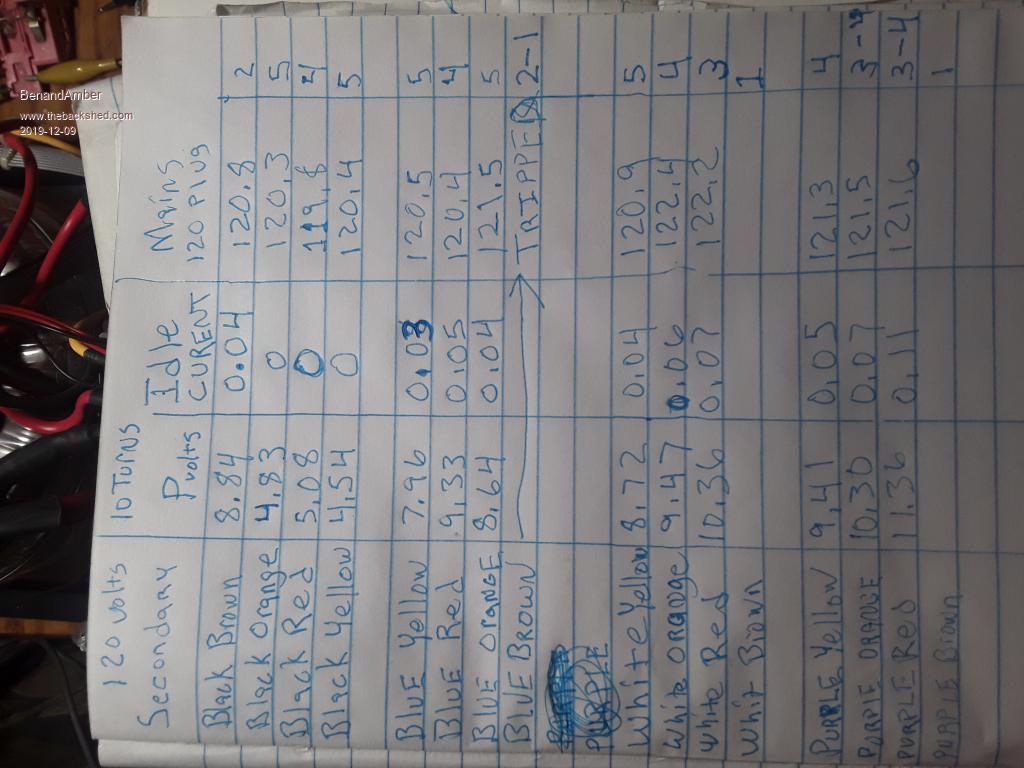 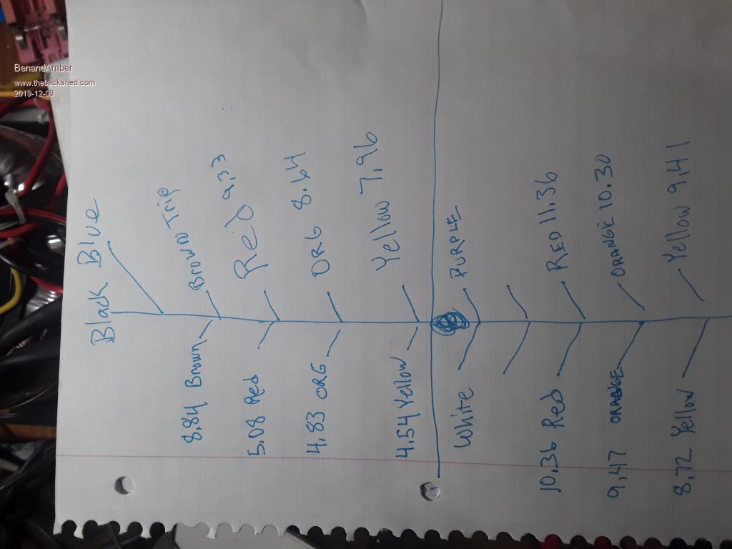 This post is kind of like learning how to fish instead of asking for a fish Thanks and have a blessed day be warned i am good parrot but Dumber than a box of rocks |
||||
| Warpspeed Guru Joined: 09/08/2007 Location: AustraliaPosts: 4406 |
I have the paperback edition of this book. Its very good hands on type information, with a minimum of mathematics. Highly recommended, and less than twenty dollars. https://www.amazon.com/Practical-Transformer-Design-Handbook-Lowdon-dp-8183333036/dp/8183333036/ref=mt_paperback?_encoding=UTF8&me=&qid= Cheers, �Tony. |
||||
| PeterB Guru Joined: 05/02/2015 Location: AustraliaPosts: 669 |
G'Day All The rule of thumb I was given for 50 Hz transformers is 7 turns per Volt for 1 square inch. To apply this you need to measure the area of the centre leg and divide 7 by that area. for example, Some time ago Ben had a transformer with a centre leg 2 x 3 = 6 square inches. If you adjust things for 60 Hz it gives 1 turn per Volt and that is what Ben said he removed. Another rule is, the primary and secondary should be of equal volume / size. Another rule is fill the window. Thickest wire possible. As for idle current, an unloaded transformer is a simple choke with an inductance of L Henrys. That gives a reactance of XL = 6.28 x 60 x L ohms and will result in a current of E / XL = 120 / XL Amps (that's for the funny US system). If I was clever I could tell you how to calculate the inductance of an iron cored choke but I'm not. Good luck Peter |
||||
| BenandAmber Guru Joined: 16/02/2019 Location: United StatesPosts: 961 |
Thanks Peter you were 100% accurate about that transformer I stripped all of the wire off of it painted it with Transformer paint and rewound it with yellow wire It was a 220 Transformer before and had three separate windings horizontally I wound it as a single large 120 volt winding this gave it alot more room so I just kept on winding I may have to take a few turns off of it I'm trying to get my head wrapped around how this will affect it Warpspeed I really appreciate the suggestion I am going to go buy it right away I collect up as much stuff as I can get free or cheap Please don't hesitate to ask if there's any thing any of you may be looking for I may just have it or be able to find it and it's most likely going to be free you guys are awesome thanks again and have a blessed day be warned i am good parrot but Dumber than a box of rocks |
||||
| PeterB Guru Joined: 05/02/2015 Location: AustraliaPosts: 669 |
At the risk of driving you up the wall and I hope that expression is understood. A transformer is usually designed by working out the power level required then you take into account the number of secondaries plus a few other odds and sods and then you consult your catalogue to find a suitable core which you then get from the store. However in the real word If you start with a core that will determine the turns per Volt. The window area then determines the maximum size of wire that can be used to fill one half of the space. The size of wire then determines the maximum current that can be used. From memory, 16 SWG is good for 4 Amps. So then you know how much power you can get from that particular core. But then, If you play with the number of turns, more turns means lower idle current but higher resistance loss. More turns will also reduce iron loss (I think). All of the above is for good transformer design. The Chinese are very good at pushing things to the limit with the result of high temps etc. I hope this helps. Peter |
||||
| BenandAmber Guru Joined: 16/02/2019 Location: United StatesPosts: 961 |
The Square Transformer with yellow wire is wound in such a way it can be a single winding ,center taped ,or 2 in hand Each end of the winding has two wires 12 gauge AWG type thhn We Strung the pair of wires out 175 feet across our yard that's around 350 feet of wire all together We didn't count the turns we just kept winding until night fall We cut both the wires so we could bring the transformer in Later on that week we soldered both the wires back on that we had cut previously Then finished winding the rest of the wire Did I mention the core was epoxied together so we wound it like a toroid No shuttle just pulling the wire through Amber was ready to kill me !!! I told her she was saying we needed to spend some quality time together she just kept on say never again benjamin never again LOL !!! Now anytime I mention Transformer she gets her panties in a bunch Just writing this has got her fired up What would any good hillbilly do the Core was free wire was free had no use for either Waste not want not right? This might be a good time to look up the terms Jack leg or West Virginia hilljack I figured this would give us a little bit of flexibility to experiment with because both wires are the same amount of turns As far as amperage that the two 12 awg thhn wires can handle I'm not sure It would be 40 amps on regular household wiring on a shorter run I have looked up so many amperage guides online and they're all different Some say you use the chassis grounding guide that's a little scary to me Reminds me of a factory power jack Transformer written down in my notebook i have what warp speed said about wire size and amps off the top of my head I think it was 8 amps for every 4 millimeter squared Don't quote me I would have to look it up I am probably wrong I have went by the book on all the toroidal Transformers Well close anyway Just using what was free on this experimental Square One Couple of nights ago I tried this formula on the internet for estimating wattage on E I Transformers I'm not sure how accurate it is it came out to under 1500 watts for this core It is a fun hobby for us and if we can help somebody out along the way it's that much better be warned i am good parrot but Dumber than a box of rocks |
||||
| PeterB Guru Joined: 05/02/2015 Location: AustraliaPosts: 669 |
You two have something very special. Peter |
||||
| BenandAmber Guru Joined: 16/02/2019 Location: United StatesPosts: 961 |
Thank you Peter for the kind words Not much going on on the back shed not in Electronics anyway I think I'm going to juice it up a little bit next month I want to buy one of them $30 4 mosfet China inverter boards I am going to change out the mosfets to the highest amp mosfets I can find Redo the tracks bulk them up really big and put some really big caps on it I'm also going to use a oversize Transformer I would like to see how high I can get the output wattage Of course I'm going to do this on the smallest budget possible I would like to get 3000 Watts continuous I have seen 23 amps on the 120 volt output of the first one I built It was very short like when starting a saw I have heard people say that they will do 2000 Watts all day long if you have a good fan on them I think first of all I'm going to learn how to program a nano I put it off for far too long I also have those little power jack boards I need to try out I am currently trying my best to fix a old tektaonix 465 The left side of the screen works fine I hook it up to the calibrator and can see the square wave perfectly There is something wrong with the horizontal sweep it will go no further than the center of the screen All of the power rails voltage are good except for the - 8 volts it is -6 volts Some of the disc capacitors on the board will show some continuity through them like a resistor and others don't Need to figure out if this is normal or not I'm in way over my head but I'm determined I absolutely positively will not be able to afford one for �quite a while �if ever So I'm going to try my best to fix this one it sucks not being able to see the sine wave output of a inverter that you build I figured I would blabber a little bit since no one else seems to be doing so Edited 2019-12-15 17:59 by BenandAmber be warned i am good parrot but Dumber than a box of rocks |
||||
| renewableMark Guru Joined: 09/12/2017 Location: AustraliaPosts: 1679 |
Ben, if all you want a machine to do is display a clean wave or show you if it's crap, a little lcd unit will do that just fine. That's all I have. Something like this Cheers Caveman Mark Off grid eastern Melb |
||||
| PeterB Guru Joined: 05/02/2015 Location: AustraliaPosts: 669 |
Nark That is a very good idea. I wish I had thought of it first. It will help B&A fix the 465. On the subject of which, there is a lot of info on that on GOOGLE. It was/is a very popular CRO. Peter |
||||
| PeterB Guru Joined: 05/02/2015 Location: AustraliaPosts: 669 |
Sorry Mark I didn't mean to call you Nark.  Peter |
||||
| Page 1 of 2 |
|||||
| The Back Shed's forum code is written, and hosted, in Australia. | © JAQ Software 2026 |
