
|
|
Forum Index : Electronics : Chinese Inverter Board - voltage feedback and other ?'s
| Page 1 of 4 |
|||||
| Author | Message | ||||
| FFTandMe Newbie Joined: 11/10/2019 Location: CanadaPosts: 32 |
Good Day everyone! My first post here and I'm very glad I joined. I purchased a little inverter board from Ali express that seems to be exactly like the one that user "BenAndAmber" discussed in the following thread: https://www.thebackshed.com/forum/ViewTopic.php?FID=4&TID=11169 I want to take a moment before asking my questions to thank Poida as well as BenAndAmber for their knowledge, help, and useful photos both in that thread and in others for doing the mods needed to unleash the potential of this little board. I purchased this board several months ago but a work trip and several family heath scares mandated putting this on the back burner. Now that life is getting something back to normal I want to return to this project and get things going! The version of the board I purchased has 24v input. I can post detailed pictures of the board I'm holding but the link to my purchase is here: https://www.aliexpress.com/item/33030072824.html From what I can see, this board is identical to the one posted by BenAndAmber in the above captioned thread. What I'm concerned about is the feedback loop. I live in an area that uses 120v power not 220-240v. Since I plan to wind my own toroid transformer for the output I'm trying to decide how to handle this. After doing some more searching on here and a few other places it seems that the board's circuit is one of the reference circuits on the EG8010 reference sheet. If so, and if I'm reading the schematic correcty, the feedback circuit uses a resistor voltage divider to bring the voltage down to the range the EGS002 expects to see. Could someone with more knowledge of schematic reading and this board confirm this? If it is indeed just a voltage divider, I see two possible paths to proceed: a) swap the resistor values to appropriate ones so the control board sees the right voltage range. If so, resistor value suggestions requested. Alternatively, b) wind a another coil on the toroid to provide the voltage the board expects to see. The toroid I plan to buy has a spec sheet with it that includes volts per turn so wiring another coil to the correct voltage would not be an issue. As an aside, the version of the board I bought, unlike BenAndAmber's seems to have HY4008W mosfets. Based on the data sheet the markings and package type match and it seems to have good specs. That being said, if they turn out to be fakes or I do something stupid and release the magic smoke that makes them work, what would be a suitable replacement should I decide to start pushing the envelope, or are these a great choice to really start pushing the board? Any recommendations/comments welcome, and once again THANK YOU ALL for freely providing such great information and knowledge. It makes me look forward to winding toroids and upgrading my solar setup to 48v in the future (currently about 1000w of solar to a 24v battery bank) once I get my feet wet with inverter boards based on the EGS002. |
||||
| noneyabussiness Guru Joined: 31/07/2017 Location: AustraliaPosts: 527 |
You are correct with it is a simple voltage divider, i would assume all things equal, simply double the already fitted resistor values aka, the feedback transformer will output 12v at 240v so it will only be 6v at 110v etc. You could also wind a 12v feedback winding on your current transformer and feed that into the feedback bridge rectifier ... I think it works !! |
||||
| FFTandMe Newbie Joined: 11/10/2019 Location: CanadaPosts: 32 |
Hey noneyabussiness thank you for the quick response! I am a bit confused though. There is no feedback transformer on the board, nor is there one in the reference circuit that (I think) they are using. After the bridge there are 3 resistors but no transformer: 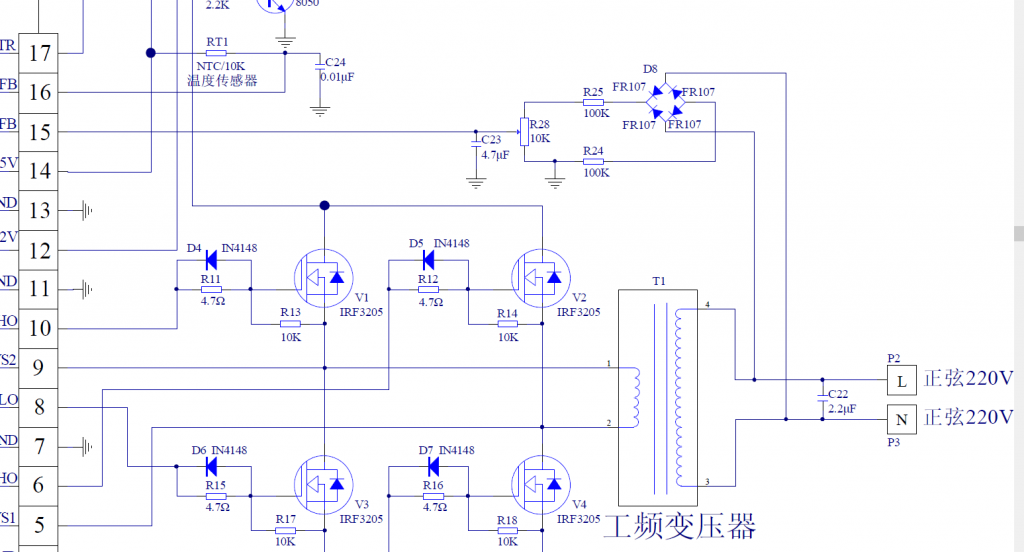 I looked at the colour codes and with my tired eyes they dont match what I have. I'll have to break out the multimeter when I get home from work tomorrow to confirm. 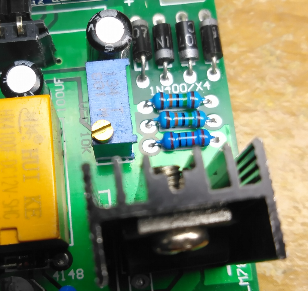 |
||||
| FFTandMe Newbie Joined: 11/10/2019 Location: CanadaPosts: 32 |
So I re-read the thread I linked above and on page 3 BenandAmber discuss the resistor values they changed but I can't follow it. I'd appreciate it if someone can clarify which resistors they changed. At first I thought they changed the trimpot to 40k but that may not be the case. Thanks! |
||||
| tinyt Guru Joined: 12/11/2017 Location: United StatesPosts: 561 |
Based on BenandAmber's thread and your picture, the top resistor is 150K, the middle resistor is 150K, and the bottom resistor is 10k. The trimpot looks like 10Kohms in rheostat configuration (the wiper is connected to one of its outer terminals). This 10K rheostat is connected in parallel to the 10K resistor. So, these components are not connected exactly like those in the EGS002 data sheet shown earlier. The connection is: Bridge + -> 150K +-> � 10K � � +-> 150K -> - Bridge � �EGS002 (15) <-+-> 10K pot <-+-> System Ground Assuming that the trimpot wiper is set for maximum rheostat resistance of 10K, the total resistance across the bridge is 150K + 5K + 150K or 305000 ohms (5K came from the two 10Ks in parallel). For a 220V configuration, the current through the resistors is roughly 220/305000 = 0.000721A. Assuming that the two 150K resistors are very close to each other in value, the voltage across the pot set at 10K and the 10K resistor will be. 0.000721 x 5000 = 3.6V(roughly). This will roughly be the voltage at EGS002 pin 15 (or EG8010 VFB). Note that I am using Excel to do the calculations. The voltage feedback limit of the EG8010 that is used on the EGS002 is 2.75V thru 3.15V. So, the 3.6V maximum that the trimpot can be set is just slightly higher to the 3.15 limit (EG8010 VFB max limit). For 120V configuration: If the 10K resistor is changed to 39K per BenandAmber's thread, VFB max from the trimpot will be 3.10V. If the 10K resistor is changed to 47K, VFB max from the trimpot will be 3.21V. If the 10K resistor is changed to 100K, VFB max from the trimpot will be 3.53V. I think you can change the 10K to any value from 47K thru 100K. And if you set the trimpot so that VFB is within the limits, you are good to go. Edited 2020-01-16 05:09 by tinyt |
||||
| FFTandMe Newbie Joined: 11/10/2019 Location: CanadaPosts: 32 |
My goodness tinyt! Thank you so much for such a concise, clear explanation. I was looking at the circuit board and I agree with your assessment of the resistor values, but it didn't make sense what they were doing. That makes it very clear and helps out a ton. I just got in from work so I am going to eat some food and then play with the board using my meter just for the fun of it and get more familiar with it. I'm looking forward to playing with the board even if I release the magic smoke as I am ordering a bunch of parts tonight including the mod parts poida suggested in the other thread. Cheers! |
||||
| BenandAmber Guru Joined: 16/02/2019 Location: United StatesPosts: 961 |
Poida the great walked me through my first build I would have gave up with out his and Mark's encouragement I thought I knew more than I did when first started After realizing I knew very little I swallowed my pride and then re-read everyone's post very carefully I realized there was several incredibly talented experts that have a lifetime of experience and thay are trying to help me I also realized Electronics is not one of those things you're going to master quickly it takes a lifetime to become a incredibly talented expert in his field These boards that's already built don't look very appealing when compared to all of the works of art you will see on here But they are the best choice for most people These boards has made it possible for people lacking the skills of these experts,to build a really good homemade inverter With all this being said I think you made a very good choice These pre-made boards are by no means perfect but anyone willing to read and follow directions can make them better with very little skills of there owe if you carefully read and take the advice of the experts on here, you will be extremely pleased with your little inverter I wish I would have done a few things different on my first inverter I wish I would have made a small board with 120to 12 volt Transformer for the voltage feedback This small board could have a few other things on it also if interested ask around A bigger heatsink is always a good thing I think the really big caps I put on mine is one of the reasons that it does so well I have been told 4 hy4008 mosfets will do 2000 watts all day with the right cooling My little inverter has done well over that for short periods like starting a load Good choke big heatsink big caps big wire and big Transformer core are good things to keep in mind The well thought-out and perfect layout inverters on here is what I strive for You will see inverters on here that are laid out perfect and engineered to look like a piece of art I have built 9 of these China inverter boards so far the largest being 10000 watts After the one and only blowup that was my fault I have had no problems I have been very impressed with all of them About six thousand Watts is the highest load I have put on any of them so far It takes a very big battery bank (that I do not have ) to run that much wattage for long periods of time Nice to see another new person getting inspired and taking action to build there own homemade inverter They are so much fun to build it is very satisfying to build and gain the knowledge on how to work on your own homemade inverter Peace of Mind of knowing if something brakes you can fix it and the money you will save makes it a very good hobby to get into Welcome aboard!!! be warned i am good parrot but Dumber than a box of rocks |
||||
| brucedownunder2 Guru Joined: 14/09/2005 Location: AustraliaPosts: 1548 |
Hi Bruce here, My small 48 volt Chinese cheap inverter gets hot after about an half hour with twin 40 watt floor light connected. Does your Chinese inverter boards get hot ,? thanks Bruce Bushboy |
||||
| noneyabussiness Guru Joined: 31/07/2017 Location: AustraliaPosts: 527 |
aliexpress board This is the board i have, its been running the house now for months... and thrown everything at it... fan barely run, even on 38� days with heaps of aircon etc... i have a oil cooled 5kw toroidal transformer on its output... I think it works !! |
||||
| BenandAmber Guru Joined: 16/02/2019 Location: United StatesPosts: 961 |
BruceDownUnder no I have never seen it hot I have ran box fan a few lights a small window air conditioner for hours along with circle saw jigsaw Sawzall charging cordless drill when needed Sometimes the circle saw would kick it into overload That circular saw on Startup uses 23 amps on the 110 outlet The 120mm 48 volt high speed fan is on if the inverter is on if it had a large heat sink I would have used cheap fan that turned on when needed On the other eight the fans have never kicked on that I have seen all of those 8 are much larger boards a lot like noneyabusiness Thay probably haven't reached half the wattage they are designed for be warned i am good parrot but Dumber than a box of rocks |
||||
| brucedownunder2 Guru Joined: 14/09/2005 Location: AustraliaPosts: 1548 |
Thank You Moneya business and Ben. and Amber,. I checked out the Aliexpress ads. and am impressed. I have the Torodial ,choke ,fans and most other hardware from my Powerstar W7 enclosure... I will scout around for a nice test enclosure.. Moneya business , did you buy the Aliexpress by it's self or do you suggest buying any of the other offered parts that they advertise ?? Did you just do a money transfer through eBay or whatever Aliexpress suggest ? Thanks Bruce Bushboy |
||||
| FFTandMe Newbie Joined: 11/10/2019 Location: CanadaPosts: 32 |
BenandAmber seeing your thread on that little board encouraged me to give it a try. I am having trouble finding toroid cores but I found one on ebay I may buy. I dont have an account but I guess I'll have to make one finally. It seems to be a high quality core and will easily handle anything this little board can throw at it even if I could modify it to handle 2000 watts. In the mean time I have a junk EI transformer I may take apart just to practice winding transformers with what I have on hand and getting used to testing for volts per turn and other techniques. I am waiting for a few this-and-that parts to arrive and once they do I can begin to get this project together in earnest. |
||||
| brucedownunder2 Guru Joined: 14/09/2005 Location: AustraliaPosts: 1548 |
FFT and me, I got my toroidal out of a inverter(the solar house type). If you find a service man or dept. that installs and repairs house solar installations, they more than likely have heaps of junked inverter (tip.- tell the guys the ones you most likely find a "Torodial" in are the real heavy ones !!!. They will know, cause most today are the transformer-LESS ones installed, simply because they are less weight. Get one and search my "backshed" a couple years back and I tell you how I stripped mine and rewound it .. best of luck Bruce Bushboy |
||||
| FFTandMe Newbie Joined: 11/10/2019 Location: CanadaPosts: 32 |
Thanks Bruce! Im quite rural so there arent any solar installes near me (closest is over an hour away) and from what I see he only carries HF inverters that are mostly grid-tie. I may check ebay for broken ones but either way its going to be a fun project regardless. How do you search for a specific "backshed"? I didnt see a search function here |
||||
| lizby Guru Joined: 17/05/2016 Location: United StatesPosts: 3799 |
One possibility on google (though not very specific): Bushboy toroid site:https://www.thebackshed.com/ ~ Edited 2020-01-20 04:30 by lizby PicoMite, Armmite F4, SensorKits, MMBasic Hardware, Games, etc. on FOTS |
||||
| FFTandMe Newbie Joined: 11/10/2019 Location: CanadaPosts: 32 |
oh right on... i thought there was an explicit search function on here that i missed. |
||||
| Warpspeed Guru Joined: 09/08/2007 Location: AustraliaPosts: 4406 |
There is a search function, right at the top left hand corner of this page. I notice the more clued in Chinese are now recommending a choke. They are learning. The oil cooled transformer sounds interesting, what kind of oil are you using Nonya? Cheers, �Tony. |
||||
| brucedownunder2 Guru Joined: 14/09/2005 Location: AustraliaPosts: 1548 |
FFT and me + otherlurkers The Torodial 's are mainly available on the older style SOLAR grid-tied inverters. not your domestic solar inverter. So, your friendly installer will know of these. The "Backside search" , I'm a bit of a dunce on all things computer , so I just go get a cup of coffee and settle down to a lengthy session searching Brucedownunder2 -the 2 is important or just copy and paste my name .. Lots of things there from my long past . Also if you go to"ENERGYMATTERS" you will find my contribution under the name of solar@wind , another great solar and wind site. Cheers, Bruce Bushboy |
||||
| BenandAmber Guru Joined: 16/02/2019 Location: United StatesPosts: 961 |
I saw a video on YouTube of a guy making a toroidal Transformer out of a electric motor's laminations It worked but he never checked the efficiency of it After that I did a Google search on DIY Transformer core I read about 4 different possibilities The electric motor laminations stator A car alternator stator laminations may be able to use the existing windings powder iron mixed up with a resin put in mold and last but not least soft iron wire All of these are supposed to work what kind of efficiencies who knows until you try it Some of the sites were bragging on how well they work Just a few silly ideas off the internet be warned i am good parrot but Dumber than a box of rocks |
||||
| noneyabussiness Guru Joined: 31/07/2017 Location: AustraliaPosts: 527 |
I use hydraulic oil, i know its not " transformer oil" but has a good dielectric strength and very little water ingress... has worked flawlessly for months... I purchase a lot through aliexpress, very reliable.. had a problem with some very out of spec mosfets.. complained and aliexpress refunded, even though the seller wasn't coming to the party.. they don't get funds until you confirm that you have received items... I think it works !! |
||||
| Page 1 of 4 |
|||||
| The Back Shed's forum code is written, and hosted, in Australia. | © JAQ Software 2026 |
