
|
|
Forum Index : Electronics : Chinese Inverter Board - voltage feedback and other ?'s
| Author | Message | ||||
| Murphy's friend Guru Joined: 04/10/2019 Location: AustraliaPosts: 580 |
Regarding your problems winding heavy gauge wire onto a torodial core, yes you WILL have problems using a shuttle doing this. Much thicker wire (15mm sq) has been wound by hand (and soft faced mallet) in one long thread on this forum. That builder used the 'bicycle rim' method sans the rim as that wire was stiff enough to self support. You would do well reading "building an inverter from scratch" that started posting in 2018 I think. Unfortunately the original poster is no longer here, got a gut full of the resident troll on this forum I'm told. |
||||
| FFTandMe Newbie Joined: 11/10/2019 Location: CanadaPosts: 32 |
Hi Murphy! Thanks for the thread! That was one I missed when I was scrolling here a few months ago about my inverter board. Im only on the 2nd page so i'm looking forward to getting through it. |
||||
| tinyt Guru Joined: 12/11/2017 Location: United StatesPosts: 431 |
After buying a few magnet wires with different insulation colors, I have observed that the red colored ones are easiest to bend. One vendor even described it as soft anealed. I don't know if there is a color coding scheme for magnet wires. Just sharing my limited experience. |
||||
| Warpspeed Guru Joined: 09/08/2007 Location: AustraliaPosts: 4406 |
There are various types available, and the difference is in the insulation. The really good stuff is a dark brown (polyester-imide insulated) rated for 200 degrees Celsius. Its tough stuff, and stripping the insulation off for soldering a real bugger. Now there is low temperature coil winding wire, often a much lighter pinkish colour, and that is made to be very easy to solder. A soldering iron just melts straight through the polyester insulation. This is made for non power applications, such as radio frequency coils, and audio transformers, relays, and similar cold running applications. Do not try to use this low temperature stuff in a power transformer ! It will fail the first time it gets really hot. I have sometimes seen green coated wire, that is used where its convenient to identify different windings, but the temperature capability of that is not known. Stick with the heavy duty 200 Celsius rated imide wire, its always used in transformers and motors and other high temperature applications, and its the most commonly used type so there should be no trouble finding some. Now once you have wound your first two 190 turn layers, its time to check that they have an identical turns count. First connect one winding across your 120v 60Hz supply. It may be interesting to check the no load magnetising current, which will be a very good indicator to your inverters final zero load idling power. A rough guess might be around 20VA to 30VA for something of about that size running at one Tesla. Now there are two ways to check that there are equal turns on both windings. One way is to measure the voltages across each winding. They should(?) be equal but never are exactly equal. A one turn difference should give +/- 625mV difference. If you common one end of both windings and measure across the free ends, that will give a more sensitive voltage reading. The other way to check for equal turns is measure the transformer idling current with just one winding. Then measure it again with both windings connected in parallel. There should be no change. If there is a one turn difference, that will act like a shorted turn and cause an unmistakable increase in transformer idling current. I recommend you do this test for each new layer before proceeding with the next layer ! Edited 2020-04-15 07:19 by Warpspeed Cheers, ĀTony. |
||||
| FFTandMe Newbie Joined: 11/10/2019 Location: CanadaPosts: 32 |
Warpspeed, I do indeed have 200C magnet wire. I made a point of buying wire that was rated for that. Let me say winding my first wind yesterday was quite an experience, both because I haven't wound any coils whatsoever in years and because this is my first toroid wind ever. It was challenging to get equal spacing of each turn and I rewound the first 20% of the coil about 3 times before I got into the groove of how to proceed. I'm pretty excited now that I have one turn done. And thank you for the help in testing. That was going to be my next question. After I wound my first winding I put the coil down and slept on it. Then, using a magnifying glass, a good light source, a fine pointer and some masking tape, I would count and mark turns as I went along. I repeated this several times until I got the same count more than once to ensure I was right. This may be more challenging as winds go on so I will practice using your method as well. I also read about using "the lightbulb method" on here. I'll have to find it again so I can show you what I was talking about. As an aside, I SEVERELY overestimated the amount of wire I needed on the shuttle and as I look at it, I'd say I have about 10-12m of wire left on it. I suppose its better to have too much than have too little and forced to make a solder joint (even though I'm not the greatest winder I'd still like to have it as clean looking as possible). I have one other question for you (and the forum) if you'll indulge. I've seen a couple of options for treatment of each wind. I've seen people suggest a thin coat of epoxy on the wind and I've seen others say to wrap in mylar tape. I'm a bit leery of epoxy solely because if I make a mistake I've made the mistake "permanent" and I'm having trouble finding mylar tape that doesn't have an aluminum coating so I'm not sure what to do (I'm kinda looking in your direction Benandamber :). My local store has silicone tape rated to 500C but from my experimentation with this tape on the thicker wire it doesn't have the greatest tensile strength and the tape is rather thick which may result in not getting as many winds on as possible. Suggestions/ideas appreciated. |
||||
| FFTandMe Newbie Joined: 11/10/2019 Location: CanadaPosts: 32 |
I think I found something... Polyester Film Tape, 200C rating What do you think of this? They have different widths but I'm more interested in the insulating and temperature properties. |
||||
| Warpspeed Guru Joined: 09/08/2007 Location: AustraliaPosts: 4406 |
Three inches wide might be very difficult to handle winding around a toroid, and the price is outrageous. Polyester general purpose packing tape made in China is exactly the same stuff and its really cheap. I bought a six pack from the local hardware store, cannot remember what it cost but it was only a few dollars. Its incredibly thin, very strong, and has very good electrical properties. I also just very quickly found this on e-bay. 24 rolls for $25.00 Its very narrow, but its the right stuff. Should be readily available almost anywhere at very low cost. https://www.ebay.com.au/itm/Scotch-3-4-x-60-Yds-Clear-Polyester-Film-Packaging-Tape-24-Rolls/254398992786?hash=item3b3b5c9192:g:PgcAAOSwvbRdsbmY Anyhow just found this interesting online calculator. According to this calculator, when you reach your final 65mm hole diameter, it should be possible to fit 24 turns of 11mm outside diameter into that. Exactly like this: 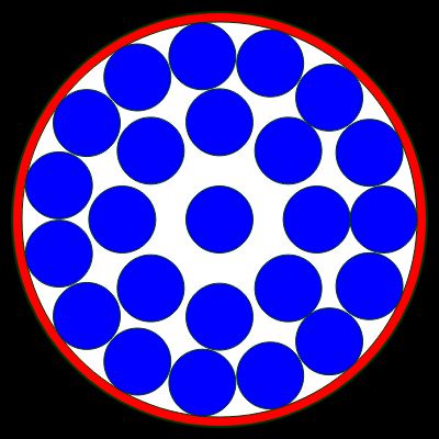 https://www.engineeringtoolbox.com/smaller-circles-in-larger-circle-d_1849.html Edited 2020-04-17 09:15 by Warpspeed Cheers, ĀTony. |
||||
| FFTandMe Newbie Joined: 11/10/2019 Location: CanadaPosts: 32 |
Thanks Warpspeed! They had various widths I used that solely for an example. If packing tape has the same properties I'll be hitting my local store and pick up some narrow tape. That calculator is invaluable! I'll be measuring the heavy wire I have on hand to ensure its OD is 11mm (or slightly less) so I am assured of getting the right fit (assuming I decide masochism isn't for me and try to parallel wind some of the thick magnet wire I have on hand). On a side note, I've got a full plate of "honey do" things this weekend and just scored 1.5kw of solar panels at a good price (by Canadian standards, anyway) so the coil might go on standby while I get them installed. I need the power generating capability right now as I migrate off grid and I also have 23kWh worth of batteries arriving on Tuesday. -D |
||||
| Warpspeed Guru Joined: 09/08/2007 Location: AustraliaPosts: 4406 |
One other nice little trick someone else here thought up. Once you know your required primary turns, go out and buy some rope of a similar size, and check that it fits, and it will also tell you the length required. Welding cable can be fairly expensive, so knowing the exact length required can be a big help. If it all looks too difficult, try 24 + 24 turns of something thinner. Cheers, ĀTony. |
||||
