
|
|
Forum Index : Electronics : Pulse Driver for Irrigation Controller
| Author | Message | ||||
| Solar Mike Guru Joined: 08/02/2015 Location: New ZealandPosts: 1228 |
Part of the control system at our new site works with Irrigation Controllers, these are nothing more than fancy time clocks with multiple outputs, usually min of 4 outputs, some have expander modules; most work off 230 Vac and output a 22 Vac signal to energize a AC solenoid on a water control valve. As our site is totally off grid and have various other in house control and monitoring systems all running from a 12 Vdc backup battery, it would be preferable to use solenoid valves that were DC actuated; we have opted to use DC pulse control valves, apply a 12 volt 2 - 3 amp 100mS pulse to open and a reverse polarity pulse to close. There are numerous valves and powered 24/7, so pulse control is efficient and keeps cable sizes down. These irrigation timers are expensive, pulse types very and not readily available, thus the rational to make a small interface pcb that can be potted, to allow use of the less expensive AC controllers or multiples of the cheap rail mounted timers with a relay contact running off 12 volts. The Pulse drive electronics has to be something like an H-Bridge set of transistors so the drive polarity to the relay coil can be reversed; after a bit of a head scratch, I decided to use H-Bridge chips used to drive small dc motors, need something that will output 3 amps, will protect itself, current limit and easily controlled, came up with these DRV8871 Link , easily obtainable from the TI shop. Their ordering setup is fast, 3 days from order to arriving in the letter box. Here is the circuit, wanted opto isolation from whatever controller timer is being used and simple logic, so opted for Pixaxe 08M2, there probably would be a way to do it with 555 timers etc but a single cheap CPU seemed easier. 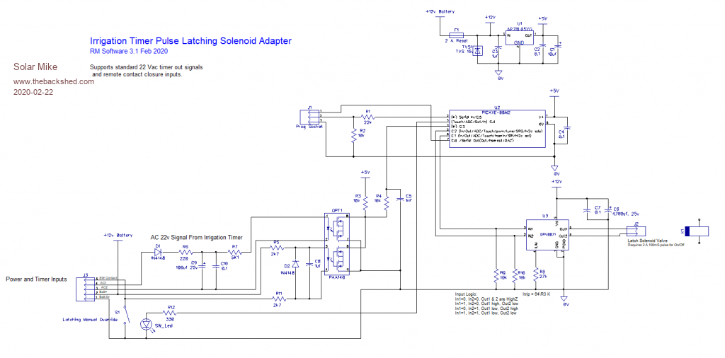 Cheers Mike |
||||
| Solar Mike Guru Joined: 08/02/2015 Location: New ZealandPosts: 1228 |
Thought it might be an interesting exercise to design similar functionality without using a CPU and specialist Full Bridge Motor driver chip. The smd versions of the Picaxe chip are difficult to get here in NZ, no one seems to sell them, so wondered if there was an alternative design that was easy to make, no CPU. Figured the solenoid pulse can have its polarity swapped for Open\Close events rather than using a hard to get motor driver chip, using a DPDT pcb relay, RS has one for $4 that has 8 amp contacts; noting its more expensive than the IC driver. My parts bin has a lot of these schmitt trigger Nand gates, some 35 years old, guess I once figured you can build anything using NAND gates and as they work up to 18 volts, then they will work fine on a 12 volt battery, saving a 5v regulator. At power up the flip flop latch is reset making sure its in a known state and the relay is off, A timer or manual switch Start Irrigation event sets the latch turning on the relay, this event is delayed to allow the contacts to stop bouncing then a mono-stable generates the 100 mSec pulse to the solenoid latch, at the end of the 100 mSec pulse the event is delayed then the latch reset, turning off the relay, saving battery power. At the end of the Irrigation period the mono-stable generates the same 100 mSec pulse but opp. polarity, latch stays in the reset position. Will design PCB for both versions, still think the CPU version will be cheaper and easier to make. 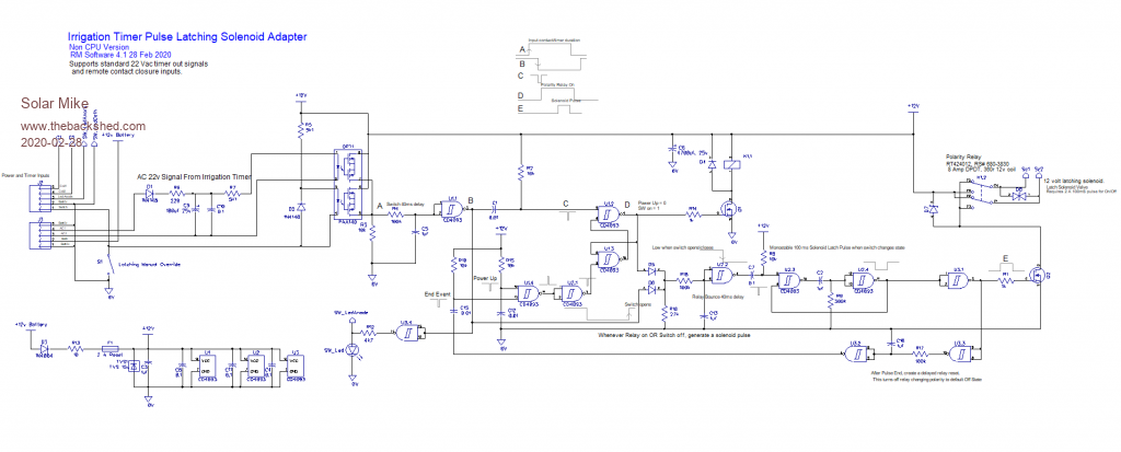 Cheers Mike |
||||
| Solar Mike Guru Joined: 08/02/2015 Location: New ZealandPosts: 1228 |
CPU Version PCB: 64 x 45mm, fits inside RS components small plastic case. 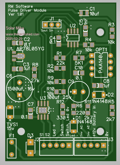 Mike |
||||
| Solar Mike Guru Joined: 08/02/2015 Location: New ZealandPosts: 1228 |
Non CPU Version PCB: 64 x 45mm, fits inside RS components small plastic case. Heaps more work to design this, had to use both sides and will take longer to build. Will plonk both designs on the same 1mm thick 100x100mm pcb and cut up with tin snips. Top: 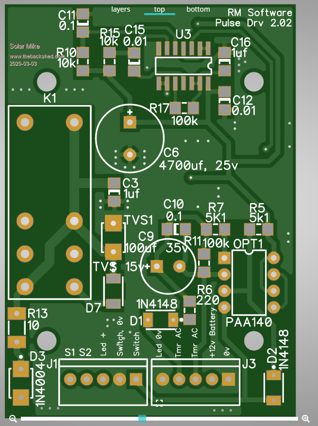 All other pcbs arrived back today, so 17 days from ordering, not bad considering. Cheers Mike |
||||
| Solar Mike Guru Joined: 08/02/2015 Location: New ZealandPosts: 1228 |
Still waiting for these boards to arrive, we went on holiday at the beginning of march for 10 days, so I had opted for return by registered post, figured they would arrive not long after; now with the total Covid-19 lock down, they seem to be stuck in Singapore, going nowhere for the past 10 days. Meanwhile.... lots of other projects to carry on with. Mike |
||||
| Solar Mike Guru Joined: 08/02/2015 Location: New ZealandPosts: 1228 |
Finally started on construction of the non cpu version. Circuit works to some extent, but was producing double pulses and limited to a tight voltage range, cut a few pcb tracks, altered some components and now working reliably for battery voltages between 10 and 15V. An external switch input from a timer, will turn on the relay, after a small delay apply a 300 mSec pulse to close the solenoid, then drop out the relay. After the watering timer ends a further 300 mSec pulse is generated opening the solenoid and shutting off water flow. Off state current is virtually nothing, on state 10 mA from Led and opto. Amended circuit: 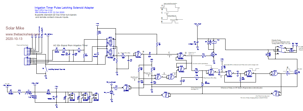 Cheers Mike Edited 2020-10-13 08:47 by Solar Mike |
||||
| The Back Shed's forum code is written, and hosted, in Australia. | © JAQ Software 2026 |
