
|
|
Forum Index : Electronics : BLDC controller using MC33039
| Author | Message | ||||
| nickskethisniks Guru Joined: 17/10/2017 Location: BelgiumPosts: 481 |
Sorry something went wrong... I prepared in word and something is wrong with copy paste I think... So there is some text missing. AHa it won't allow the arrows I used. Hi there, I’m working on a BLDC controller (short for brushless dc motor? Or ac synchronous motor with permanent magnets is better suited in my opinion), yeah endless-sphere forum would better suited for this. But why not post it here, with people that are always very helpful. It is actually a project that failed a few years ago, and I would like to improve it. I’m a little bit wiser these days, or at least I think I am. And I now think the project failed because I didn’t read the datasheet thoroughly. The section with cycle by cycle current limit and the braking feature, later more. You could say a BLDC motor controller is very different than the inverters we build. But it is actually very similar. It’s just one half bridge extra, but no fixed frequency. I would like some help with the further improvement of the design, or more like the development of a new universal halfbridge pcb that I could use for my bldc projects and later on for my nanoverter and warpverter. First I would like to show you my project and what I did, well it’s not 100% tested (I haven’t pushed the design) But it seems to be working pretty well. You can watch a video of the moving object: (I did post it also in the EV section) https://www.youtube.com/watch?v=CzqItc3o52s So I must say that I built something quite expensive with low performance, so here we start. I don’t have the knowledge to program something fancy so I used the MC33035 and MC33039 IC, it produces every signal for the 6 mosfet drivers. It has inputs for brake, reverse, forward, throttle, and the 3 hall sensors for the right commutation. It’s actually a quit simple IC if you examine it. It also has the nice feature of cycle by cycle current limit. And that’s where I got it all wrong, (I think) so what I did in the past, I had a shunt between battery and my powerpcb. That way I could measure the current, I thought that was ok. But looking at it on a closer angle I forgot that there were a lot of buffer capacitors on the powerpcb. So the ic only saw the average current. The appropriate way is to measure exactly between source of mosfet and the capacitor bank… Fault number one. Secondly, the braking function, after closer examination of the datasheet there is no current limit during this action! The ic enables all the 3 low side mosfet at ones, so all phases are shorted and the motor would stop with the current only limited to the winding and mosfet resistance. So in my case if you powering a big motor with a lot of potential energy and a small mosfet bridge, yeah that’s asking for trouble… So don’t use it, except when the mosfets are over rated maybe, or as parking brake. It’s also not possible if you think about it, the current shunt is not on the right location for doing that. The funny thing is there is a current limit if you go forward and turn the switch to reverse… I want to cut the gras and now knowing all that I want to give it a final go. (last year I did destroyed a commercial controller by shorting 2 phases). Since I had trouble to design a pcb with a resistor or hall in the source leg/ circuit of the mosfet. I was thinking why not use 3 hall sensors and measure all the 3 phase currents instead? I would probably something slower and more averaged, but I saw that all the fancy stuff on endless sphere did it like that, the only thing is, they use 3 inputs on their fancy µc, I only have 1 input… Since I now know more about basic electronics, I knew I only needed a fast quad opamp and 3 fast diodes…+ fast diode bridge to rectify the LEM signals because they are AC. And using 3 LEMs with current output, not voltage output like they are using. That’s why I call my design a expensive low performance one. To test, I made small half bridge boards, and then a capacitor board. A small board with 6 mosfetdrivers, it’s not optimal, there is some distance between mosfet and drivers, the twisted wires are helping though. For the final version I plan to make separate plug in boards something like Mackoffgrid did. Some figures: I hoped to get away with 40A phase current, but I had to adjust to 75-80A. You can easily do 80km/h with the motors on 48V, but I’m not rewinding it. I need to take the high zero torque current for going uphill with it I guess. The battery is a 10 cell(24v) LTO 20AH. With zero torque there is 6A battery current needed to create 40A phase current. You would not say but the thing will be close to 100kg! For the blade motors I will use a separate battery. Most important parts: TLP250 and FOD3182 opto mosfetdrivers IRFP064n mosfets 55V 110A 8mR LA55-p hall sensors (taken out old frequency drives) Every bridge is fused with an 20A AC breaker on the dc input. During testing I blew 2 mosfets that I replaced by HY4008 mosfets, I’m not 100% sure what caused the event, probably the breaking function… I’ve build 2 stages on one 1 aluminum plate to make it easy to mount on a heatsink. Dual powerstage: 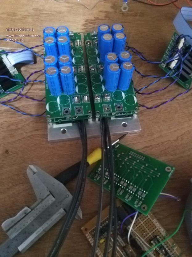 Mosfetboards: 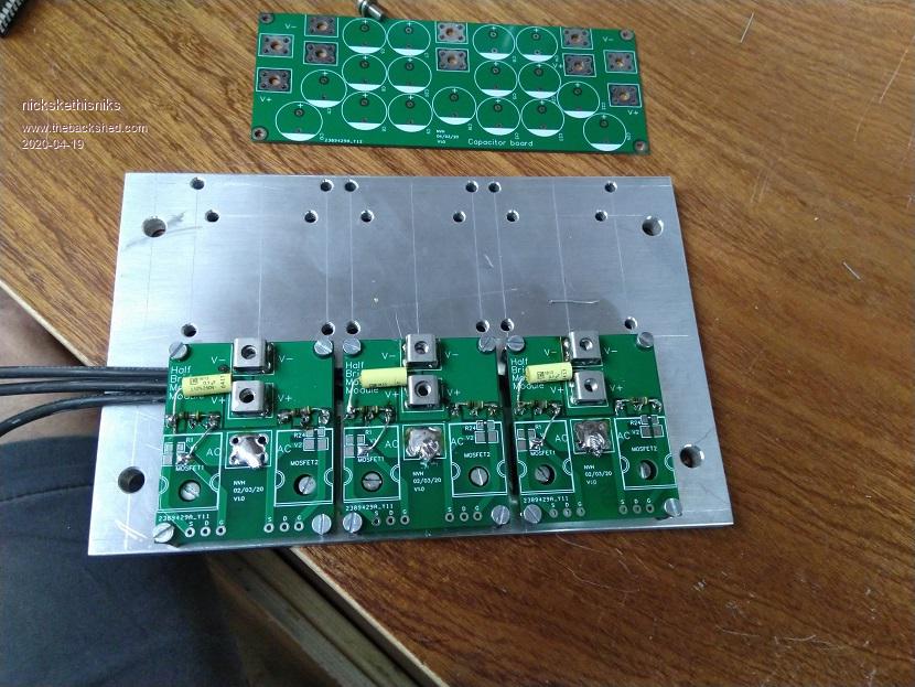 Mosfetdrives: 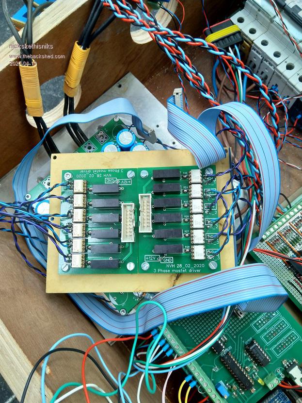 Brainbord: 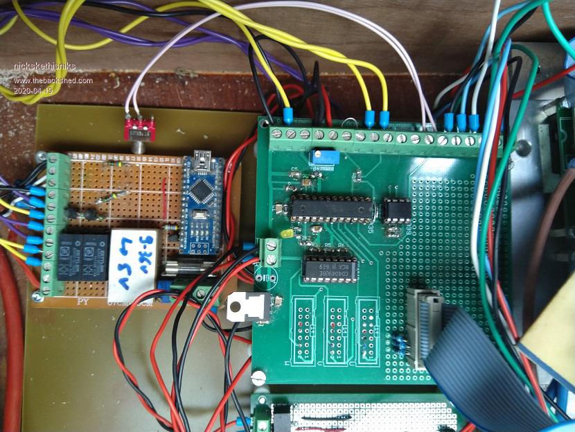 Board for conditioning the hall sensor signals: 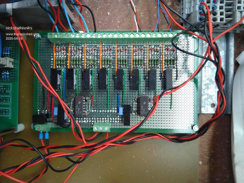 Hall sensors: 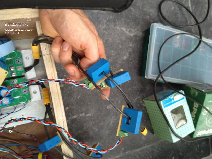 This is for now. Edited 2020-04-19 20:23 by nickskethisniks |
||||
| Solar Mike Guru Joined: 08/02/2015 Location: New ZealandPosts: 1228 |
For measuring individual peak mosfet currents you could use these IR25750 I was going to use them in both lower legs of an H-Bridge to track peak mosfet currents on a cycle by cycle basis. Cheers Mike |
||||
| The Back Shed's forum code is written, and hosted, in Australia. | © JAQ Software 2026 |
