Notice. New forum software under development. It's going to miss a few functions and look a bit ugly for a while, but I'm working on it full time now as the old forum was too unstable. Couple days, all good. If you notice any issues, please contact me.
BenandAmber Guru Joined: 16/02/2019 Location: United StatesPosts: 961
Posted: 08:46pm 11 Jun 2020
Copy link to clipboard
Print this post
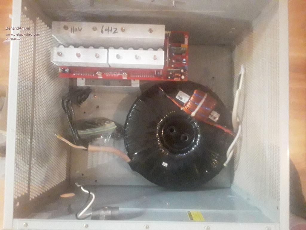
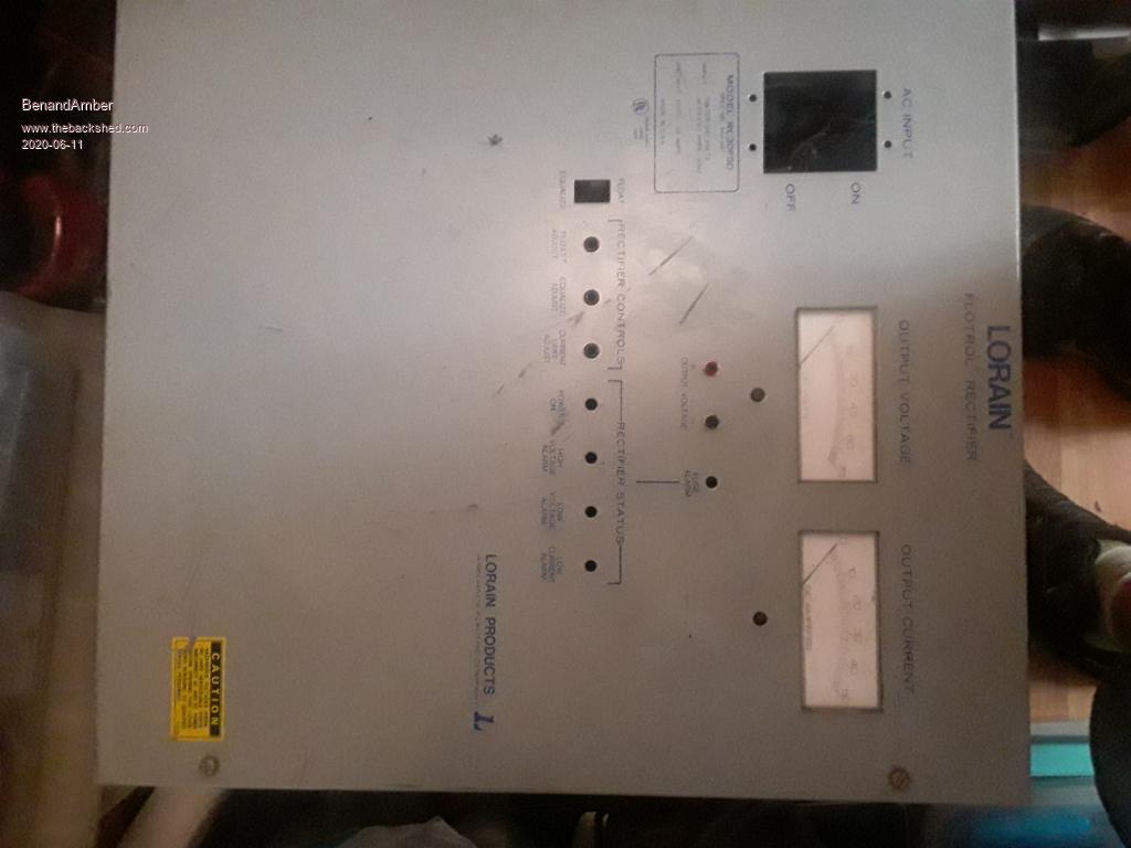
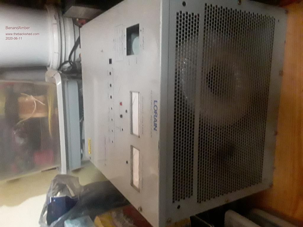
This used box is 19inch tall 17inch wide and 13deep Nice size for inverter monkey see monkey do I am not ashamed got idea from builds on here
It is heavy box been looking for box like this for months
The bottom and top are grated for air flow
Amber ordered little lcd screen with current voltage and battery power wattage It measures power in and out with the little toroid not a shunt
I ordered 2 mrpower(same as make sky blue) 60 mppt charge controllers 58 bucks each free shipping off alliexpress
Alsome deal I think!!!
I read some sellers do not include buttons and screen!!!!!!!!!!!
PAY ATTENTION AND READ DISCRIPTION MAKE SURE THE ONE YOU ORDER HAS SCREEN
From what I have read only software is different
Every one seems to be happy with them
The reviews I have read are very simuliar to make sky blue
3 stage No battery equalizing is the only complaint I have read
They come with guts buttons and screen everthing needed except heatsink and box
Was thinking about mounting them in side the box
It all depends on what you guys say
I do really apritiate the advice and wisdom
I also appreciate all the working together good hearted happy to help anyone willing to listen attitude of all of you guys!!!
And after my experiences on here because of you incredible people every time I get the opportunity
I write GOD BLESS THE PEOPLE OF AUSTRALIAbe warned i am good parrot but Dumber than a box of rocks
CaptainBoing Guru Joined: 07/09/2016 Location: United KingdomPosts: 2171
Posted: 08:47am 12 Jun 2020
Copy link to clipboard
Print this post
nice!
I wish I could do the off-grid thing. Even the images of your kit here get's the creativity flowing. You gonna keep those nce moving coil meters? very retro (and reliable)?
h
BenandAmber Guru Joined: 16/02/2019 Location: United StatesPosts: 961
Posted: 04:52pm 16 Jun 2020
Copy link to clipboard
Print this post
Captain I was planning on trying to keep them If they are very simple to use
If they require any extra Hardware or any bother at all
I will ship them to one of you guys on here that like them
U have first dibs since you commented first on them
Captain I like them but not big deal to me one way or other
I would like to send them to you!!!!
I would get more enjoyment out of giving them to you then using them!!!
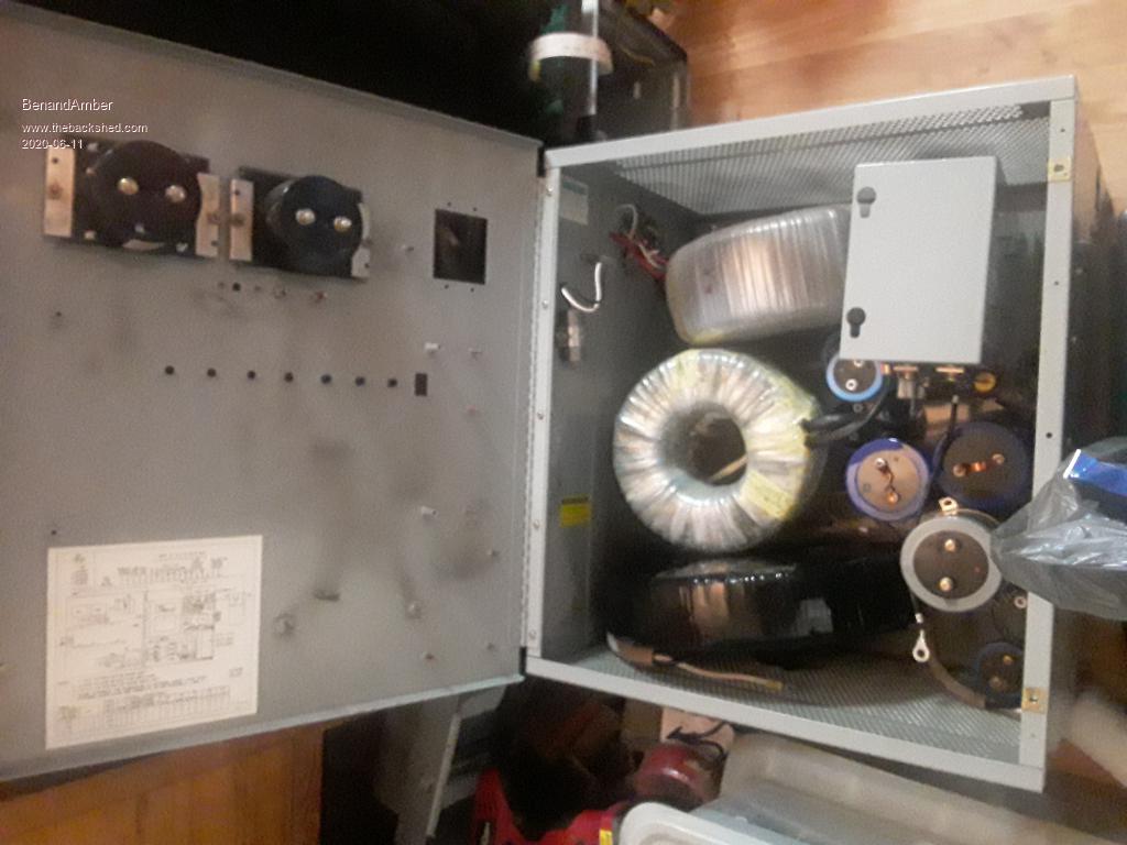
I have all the hardware that came out of the gray box I will be using for my inverter
So if there's any of the parts anybody needs let me know
I'll try to send them for free or only shippingbe warned i am good parrot but Dumber than a box of rocks
BenandAmber Guru Joined: 16/02/2019 Location: United StatesPosts: 961
Posted: 11:18pm 17 Jun 2020
Copy link to clipboard
Print this post
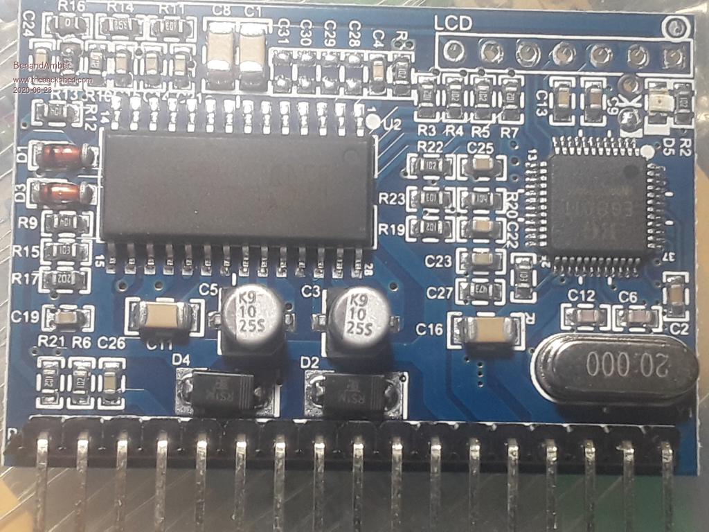
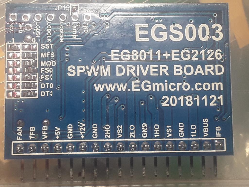
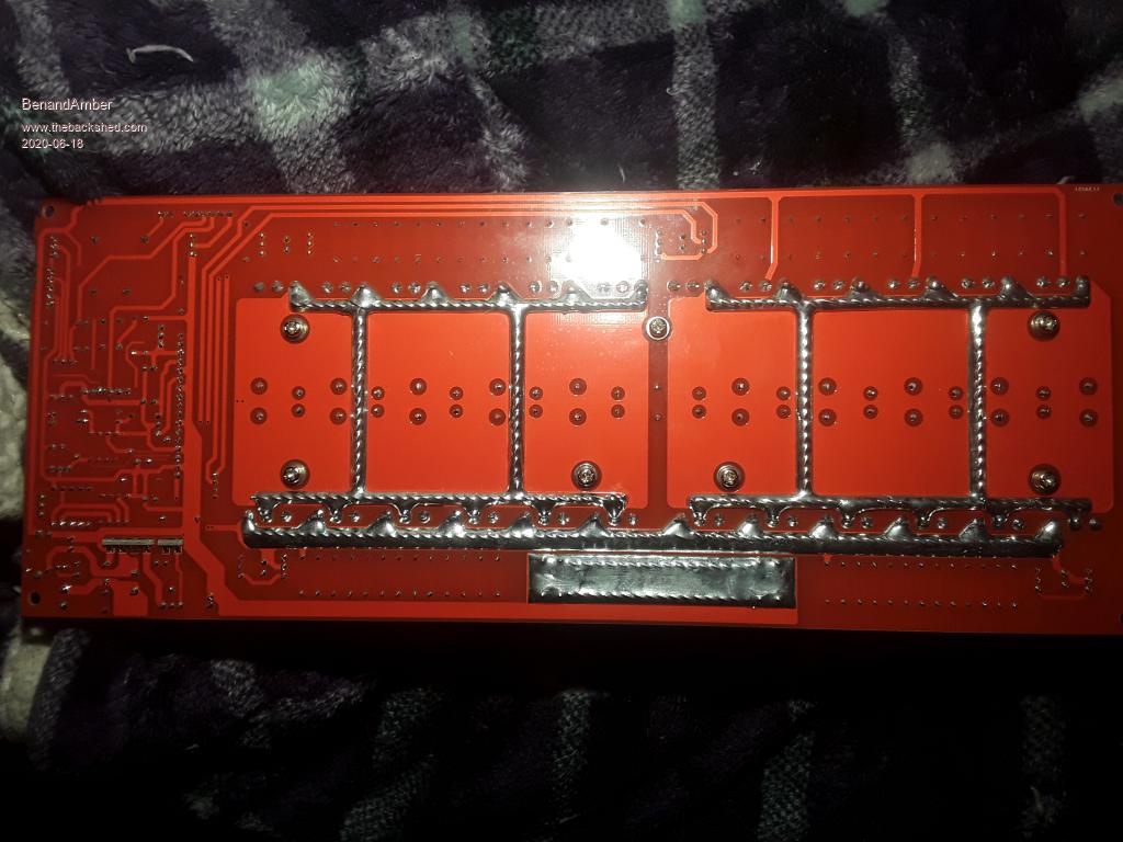
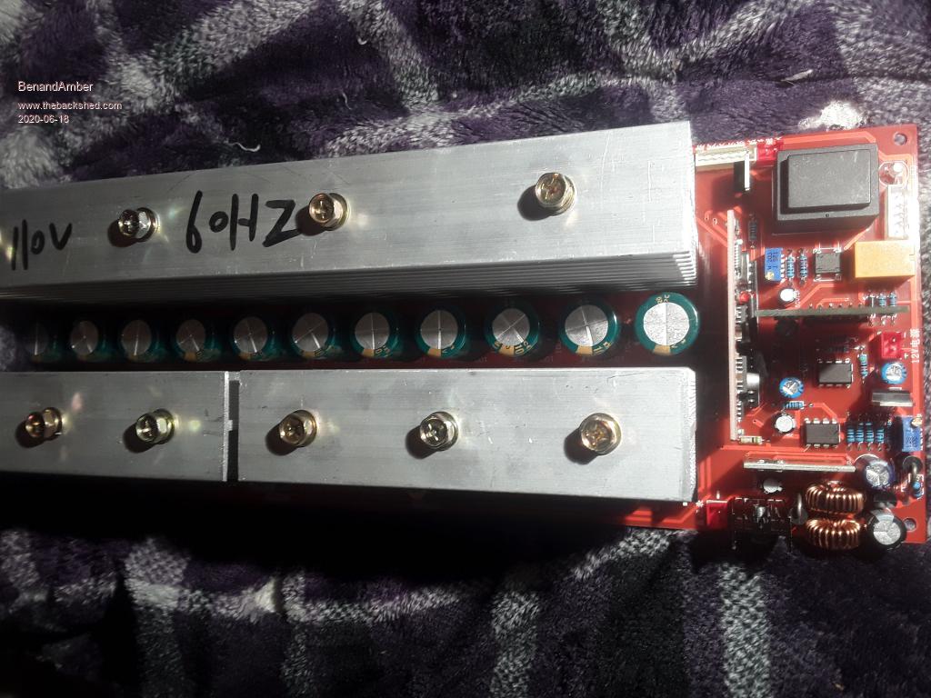
This is not the board Amber ordered thay sent the wrong one This is one of those automatically detecting input voltage boards
I thank this one maybe 12 to 96 volts
It has a wire soldered on to the oo2 board
That wire has what I think is a resistor under heat shrink
It looks like it is for something to do with current
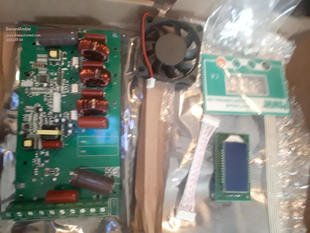
Is all them capacitors a good thing thay are only 1000uf
She ordered a board with 8 large capacitors
Thay sent this one not willing to wait and deal with exchanging it for the right one
I think this one is more expensive than the one we ordered by maybe $100 still would have rather had the one we ordered
I have those capacitors that are bigger than Coke cans I would like to use in this build
I am not sure of the best way to use the 6 crazy big capacitors
They are in a pic at the beginning of this thread
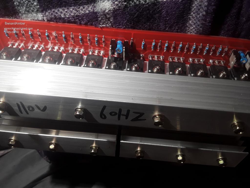
I also plan on changing the heat sinks on this board
I have some that are alot bigger
We would like to take advantage (again) of the incredible amount of knowledge of all the experts on this site
So any and all advice is highly appreciate!!!
Amber bought a large lot of Dell laptops
Most have windows 7 but need pass word that we do not have
Thay have 8 to 16 gb ram i5 processor some have solid state hard drives
Some are larger and have DVD burners other are small without CD drives
She has saved a couple back to give away to help show we appreciate the valuable advice given on this form
Only pay shipping after receiving
She has lots of extra batteries and parts also so speak up if you need anything!!!
Speak up if you have any ideas or advice on this build it will definitely be appreciated
We have drooled over all the pics of the works of art you guys call inverters for a few years now
We think by monkey see monkey do along with the well-thought-out advice you guys freely give
we can come up with something we can depend on that don't look like a jackleg built it
Thanks againbe warned i am good parrot but Dumber than a box of rocks
BenandAmber Guru Joined: 16/02/2019 Location: United StatesPosts: 961
Posted: 03:01am 18 Jun 2020
Copy link to clipboard
Print this post
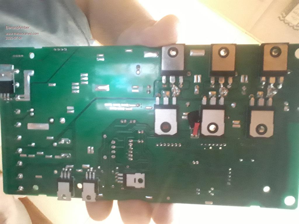
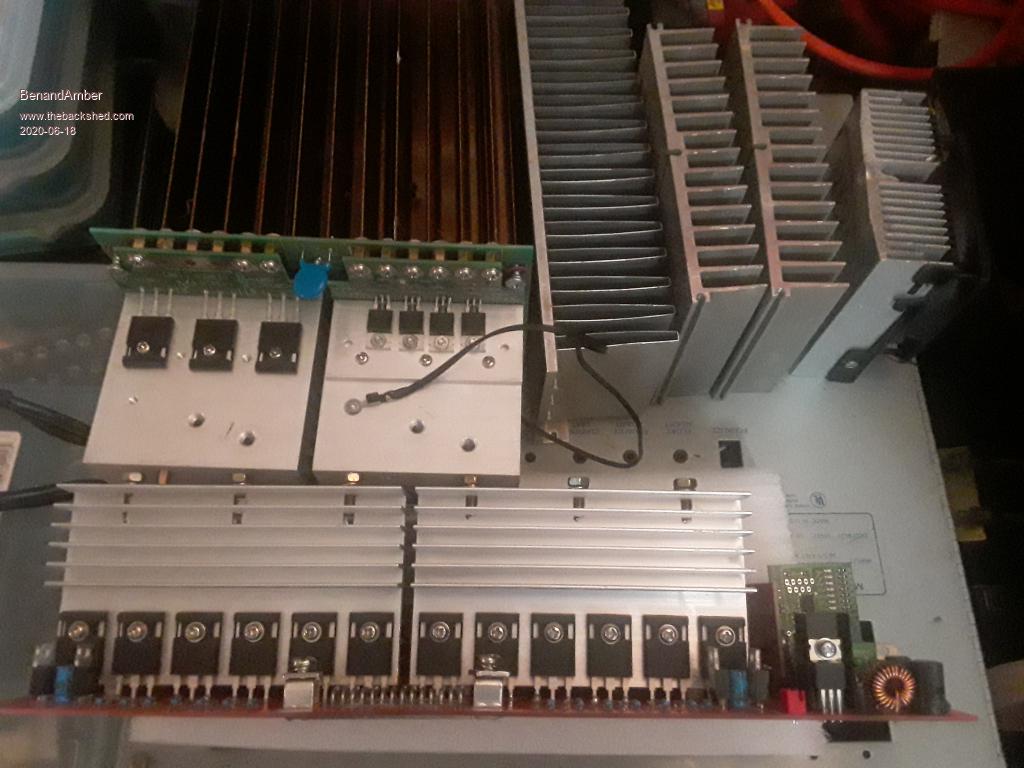
Just for comparison power Jack board and farm inverter boardbe warned i am good parrot but Dumber than a box of rocks
Revlac Guru Joined: 31/12/2016 Location: AustraliaPosts: 1282
Posted: 09:35am 18 Jun 2020
Copy link to clipboard
Print this post
Those 11 capacitors, they may be ok as is, I have no experience with that particular board. To add the large capacitors to it they should be mounted as close as possible to the mosfets (same place as the small capacitors are located) or they would have little benefit.
Looks like the POS + and NEG - is on the upper side of the PCB at the base of the capacitors. One method I can think of to add the large capacitors, would be to remove some of the small capacitors drill the holes a little bigger and attach or solder some studs or nuts on to where the capacitor were sitting. Then attach 2 copper buss bars to the studs on the underside with some spaces to keep it clear from the bottom side of the PCB to prevent any short out. Then attach the large capacitors to the buss bars, if its still possible to access the screws to put it all together.
I don't recommend the above solution as drilling the holes bigger would ruin the board and there is no going back. If it where my own I might do this only if I had to.
The heat sinks look ok Be better with some cooling fan over them, it would be easy to just bolt more heat sink on to them, it would help just a bit more. The other alternative is to put new large heat sinks on.... that would mean drilling and tapping 24 TIMES, ask anyone here, that's NOT much fun.
The cabinet looks good and should end up tidy, laying it out in the position that works the best can be a challenge.
Hope this makes sense, perhaps someone else has a better idea about the capacitor mounts.Cheers Aaron Off The Grid
renewableMark Guru Joined: 09/12/2017 Location: AustraliaPosts: 1679
Posted: 09:40pm 18 Jun 2020
Copy link to clipboard
Print this post
What's the uf value on the caps on the board? There is more than likely enough there.
Don't replace the heatsinks, just bolt something on top like Rev suggested. You'll still need cooling though.Cheers Caveman Mark Off grid eastern Melb
BenandAmber Guru Joined: 16/02/2019 Location: United StatesPosts: 961
Posted: 05:17pm 20 Jun 2020
Copy link to clipboard
Print this post
Revlac I will definitely use your idea on the bus bars
I will make it where the capacitors bolt to the bus bars then they bolt to the board
The board in the inverter at the bus runs cold without fans turning on
Thay have never turned on that I know of
The renter at the property I have bus parked on plugs in when electric is out
Mabe he has pulled enough wattage long enough to heat it up
There is only 8 140 amp hour batteries so I don't know if it is even possible
I still know very little about solar I just parrot what you guys say about it
I don't use alot of watts the air conditioner down there only uses 5 or 6 hundred watts
The board in it is pretty similar to this one
I turned it on when I hooked it up and it's been running ever since
I think a true 3000 watt inverter would work for us when I go off grid
I will be using propane fired hot water propane dryer propane cook stove and wood heat
The biggest thing will be air conditioning
We have been practicing for 2 years now
We live comfortable with a at max 1200 watt ac and a 600 watt max ac
Until recently we used a 300 watt inverter when power was out
We are not about gadgets and material things
Well except for my 13 year old son he's got TV so big you can't even see the thing
Amber spoils!!!!!! Understatmeant
How did that Transformer turn out you was building
Mark
Those little capacitors are only 1000uf each
It may just be in my head but capacitors make all the difference
The space in between heatsinks is so small no go caps will fit
We ordered a board with lots of space in between heatsinks so we could use large caps
The bus inverters board 35mm caps is to close to heat sinks
That limits the caps that can be used
That is why we made sure we ordered a board with lots of space this time
It just wasn't ment to be so bus bars sounds great
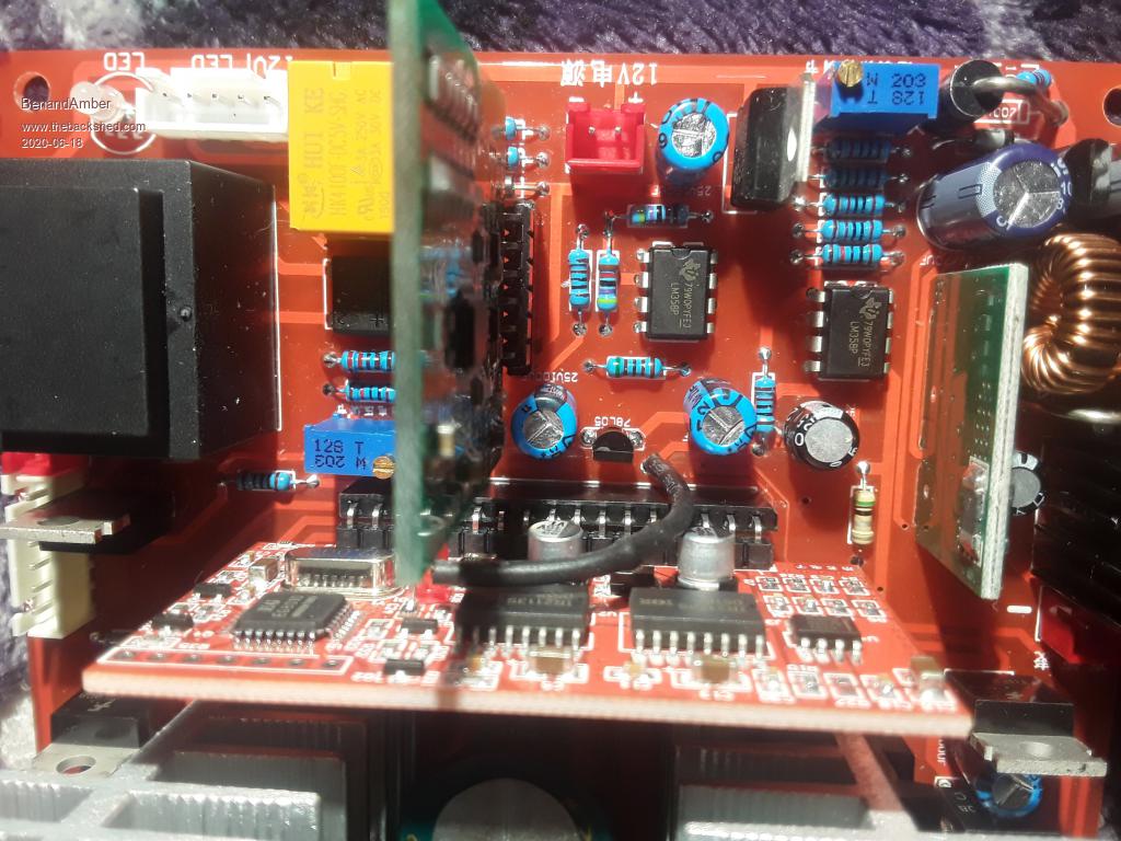
The other big question is how to get rid of that little wire coming from the oo2 board
If possible I would like to do this 1 like all the rest
The way that Poida showed me how on the first one
I don't like change especially when something's working perfect for me
I really appreciate the advice from you guys please keep it coming
Don't forget I have lots of Dell computer parts and a couple of them that just need Reloaded Edited 2020-06-21 04:12 by BenandAmberbe warned i am good parrot but Dumber than a box of rocks
poida Guru Joined: 02/02/2017 Location: AustraliaPosts: 1480
Posted: 07:25am 21 Jun 2020
Copy link to clipboard
Print this post
Hi B & A
The little wire going to the 002 board is for over current protection. There are 2 protection schemes built into the board.
The first scheme uses the current sense pin on the 002 board, and is driven by the output of the current limit comparator and trim pot. The user can set a maximum current limit using the trim pot and when that is exceeded, Ifb which is pin 1 on the 002 board is pulled high, causing the LM393 to then drive the gate drive ICs into shutdown. This happens really fast and can shutdown/enable/shutdown/enable within a uSec or so. I don't like it at all. I prefer to disable this entirely. The sudden zero to full power then zero, then full power in nearly uncontrolled manner is a bad thing. I prefer to have much slower acting current limits in place, such as DC contact breakers.
The second scheme involves the small wire plus resistor that leads up to the 002 board. Again it is a signal of over current. This time, instead of driving the gate drive IC shutdown pins, it instead drives the EG8010 IFB input. This is much nicer in that once overcurrent is detected, which is > 0.5V on the pin for 600 mS then the EG8010 stops. IT stops completely and checks if this voltage is less than 0.5V 16 seconds later. IF not, it does not start up again. If it is less, then it soft starts if enabled
So there are two over current protections. One can make the toroid jump up and down on the bench when testing. That is scheme #1. The other just works fine, but it does not handle fast over current transients.
These boards are tough and can handle the short period over current events, within reason. I prefer to disable both and limit DC input current with contact breakers. Edited 2020-06-21 17:26 by poidawronger than a phone book full of wrong phone numbers
CaptainBoing Guru Joined: 07/09/2016 Location: United KingdomPosts: 2171
Posted: 07:46am 21 Jun 2020
Copy link to clipboard
Print this post
You are a gent and a sweetheart Ben/Amber (you can argue it out between you who wants what ), and bless you for offering but it would be a waste to send them to me - I have no use for them. I hope they are easy to use and you get to keep them, failing that I am certain another off-gridder can put life back into them.
keep us informed of how this goes.
cheers
h Edited 2020-06-21 17:58 by CaptainBoing
Revlac Guru Joined: 31/12/2016 Location: AustraliaPosts: 1282
Posted: 01:21pm 21 Jun 2020
Copy link to clipboard
Print this post
Hi Ben,
The capacitors may be ok for average use, I don't know there ripple capabilities, there are a lot of them and they probably handle it better than bigger caps and less of them, I don't know, still learning about them.
I have been told one way to see if the capacitors are up to the job is to see if they get hot under load, might be good to try it first see how it performs.
Adding the big capacitors is going to eat up a lot of real estate in the inverter cabinet.
My inverter was getting a little noisy, The strap that holds the U Cores together had a little bit of insulation stuck under it, tightened up the strap and its now running silent.
I will get back on to the other transformer when I have some spare time.
Looks like something small between each of them capacitors. not sure what that is? Edited 2020-06-21 23:25 by RevlacCheers Aaron Off The Grid
BenandAmber Guru Joined: 16/02/2019 Location: United StatesPosts: 961
Posted: 05:24am 23 Jun 2020
Copy link to clipboard
Print this post
Poida That is music to my ears if I understood you correctly
My understanding is I can do this board like I did all the rest
The way you first showed me on the little 4 mosfet board
Poida or anyone else I don't know how much shipping would be on a Dell laptop
I have lots of extra batteries extra DVD burners extra solid state hard drives
It would just make my day if you could use one!!
You would have to load your own software on them because they have a password
They came from a big company and Amber bought a lot that had a sh*t ton of them in it
I loaded a old copy of Zorro that I had forgot I had on a couple of them they run great
I heard you could run Android on them
I also seen where you can bypass the password they have Windows 7 professional on them
Most have the I5 processor and 8 or 16 gigs of RAM 320 gig regular hard drive or 180 gig solid state hard drive
I brought this new style 002 board anybody know anything about it?
Some of the laptops amber bought
Try to figure out best layout
There is room under board for the large capacitors
I have one that is 9 inches long and 9 1/2 inches around
I am thinking about just adding it to the ones already on the board
It is a mepco/electra 2731-395 60000uf -10 +50% 85c 75volt 95surge
I am still thinking about putting two 60 amp mppt charge controllers in this box also
I also have 5 or 6 smart apc 1500 ups
The idle current is around 2 amps at 24 volt battery side
I tried adding a choke and it didn't help much
I am thinking about trying a toroid Transformer
If someone wants one to goof with let me know Edited 2020-06-23 15:58 by BenandAmberbe warned i am good parrot but Dumber than a box of rocks
poida Guru Joined: 02/02/2017 Location: AustraliaPosts: 1480
Posted: 06:22am 23 Jun 2020
Copy link to clipboard
Print this post
Ben, the control board is not the 002, it is a later type that uses EG's own gate drive IC. So now I think it wise to leave it all alone. I would find the trimpot that sets the current limit and wind it up to permit a lot more current before it triggers.
I need a circuit diagram of this new control board before I can possible comment much more.wronger than a phone book full of wrong phone numbers
BenandAmber Guru Joined: 16/02/2019 Location: United StatesPosts: 961
Posted: 10:54pm 03 Jul 2020
Copy link to clipboard
Print this post
The off brand 60 amp mppt charge controllers I ordered are here
be warned i am good parrot but Dumber than a box of rocks
BenandAmber Guru Joined: 16/02/2019 Location: United StatesPosts: 961
Posted: 11:04am 04 Jul 2020
Copy link to clipboard
Print this post
I finally got time to goof with the very large farm Transformer
It has 6 sets of 12 gauge wires for the 120 volt side
It has two giant wires on the 200 volt side they probly split into smaller wires
I haven't unwrapped any of the tape yet to see
My question is if on top could I unwrap turns until the 200 volt side was 120 volt also?
If so could I use it along with the other 120 volt wires?
If the 200 volt side is on bottom do I have to take it off?
Should I use the 200 volt side as 120 volts for the extra turns?
I guess I am just looking for some of that experience type of wisdom!
Sorry I get side tracked for a thought it happens more than is heathy
I can't remember what my bus inverters Transformers idle current was when plugged into 120 outlet
But it tripped the braker without the lightbulb and switch trick
The idle current after installing in the inverter on the 48 volt battery side is either. 39 or .49 of a amp around 23 watts
Is that bad?
Ok back to farm Transformer
I plugged farm transformer into my kitchens 120 volt gfi outlet
I had it wired into the 200 volt winding
The idle current was .51 at 120 volts
All 6 sets of 12 gauge wires on the 120 volt winding was exactly same voltage
First i plugged it in with lightbulb and switch then without
It didn't flip my kitchen's gfi breaker when plunging it in with out light bulb trick
I apritiate all advice
Thanks for your time!!! Edited 2020-07-04 21:48 by BenandAmberbe warned i am good parrot but Dumber than a box of rocks
BenandAmber Guru Joined: 16/02/2019 Location: United StatesPosts: 961
Posted: 12:46am 17 Jul 2020
Copy link to clipboard
Print this post
I probably all ready know the answers to my questions about my transformers
I have read about or asked almost every question before
I just like to make sure I am doing it the best I can
I hope to get a chance to work on them soon
Have a blessed daybe warned i am good parrot but Dumber than a box of rocks
BenandAmber Guru Joined: 16/02/2019 Location: United StatesPosts: 961
Posted: 12:42am 28 Jul 2020
Copy link to clipboard
Print this post
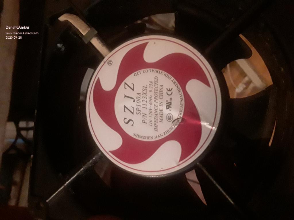
Warpspeed said a ac fan makes sense I finally ran across a 120 volt one
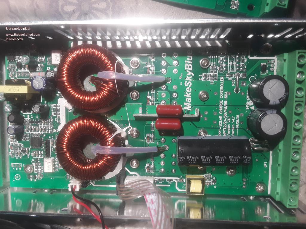
This is a newer make sky blue mppt 60 amp The board says up to 96 volts is this true Edited 2020-07-28 11:14 by BenandAmberbe warned i am good parrot but Dumber than a box of rocks
BenandAmber Guru Joined: 16/02/2019 Location: United StatesPosts: 961
Posted: 05:33pm 15 Aug 2020
Copy link to clipboard
Print this post
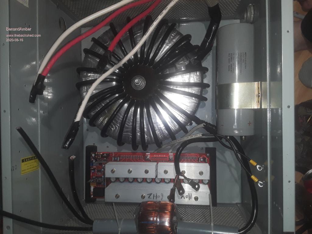
I have made a little progress on the farm inverter
As you can see we rewound and potted the Transformer
We made the Transformer so it could be used for 120 or 240
This inverter will stay permanently mounted beside the braker box
It has 2 hot legs of 120 volts and center tap (4 wires 2 connected together for center tap)
Center tap will be the neural
The metal inverter box will ground in braker box to the ground lug that goes to 2 8 foot earth ground rods
This way everything earth grounds at one place (no ground loops)
If I am thinking of this wrong please let me know
Amber said this is the last one she helps wind by hand and she really means it this time!! lol
It kicked us long and hard !!
I had it on my lap slid it off onto the couch
It sunk to the floor with lots of cracking noises
As you can see my choke is the bottle neck It has 16 12 gage wires hope it doesn't get to hot
The bus inverter has been doing great
I ran a large air compressor with it for over a hour the other day
We also was running box fans lights and other tools on and off
My big onan generator won't start the air compressor when it is up to pressure
The battery bank also did ok it never dropped below 50 volts (sun was out)
We was using so much air that the compressor wouldn't kick off for over 10 seconds at a time
It did not hesitate started everytime normally
The inverter fan never kicked on and heat sinks was barely warm
We are planning on manufacturing Transformers from scratch along with opening the store front this winter
We have been looking and pricing winding machines
We need to be able to wind at lest 100 a month for a small solar company here in the States
One day I would like to make our own inverters
With the combined knowledge gained from all of you guys (not my own)
I think I know what the future of inverters will be
I appreciate all the advice knowledge and motivation you guys have gave me!
Anything I do I plan on uploading it for review by you guys
Thanks for your time and have a blessed day Edited 2020-08-16 05:22 by BenandAmberbe warned i am good parrot but Dumber than a box of rocks
Page 1 of 2
Print this page
The Back Shed's forum code is written, and hosted, in Australia.


 ), and bless you for offering but it would be a waste to send them to me - I have no use for them. I hope they are easy to use and you get to keep them, failing that I am certain another off-gridder can put life back into them.