Notice. New forum software under development. It's going to miss a few functions and look a bit ugly for a while, but I'm working on it full time now as the old forum was too unstable. Couple days, all good. If you notice any issues, please contact me.
Revlac Guru Joined: 31/12/2016 Location: AustraliaPosts: 1282
Posted: 08:39am 01 Jul 2020
Copy link to clipboard
Print this post
Its worth looking inside of used electronic equipment for useful parts, most of it gets wasted and thrown out, quite often a member of the family would see it and say.....Why don't you get rid of that Sh*t. There comes a time when you get to tell them.... hey I had one of them and you made me through it out, now we have to go and buy one for many $$$............END OF RANT.
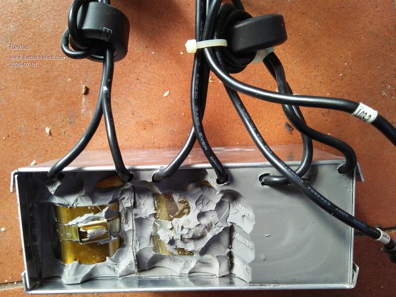
This lot is out of A SPH20 Grid Tie Inverter. It has a aluminum box full of, Well, WTF you call it, anyway after digging some of it out I could see it has a C Core Inductor on it MPPT side.
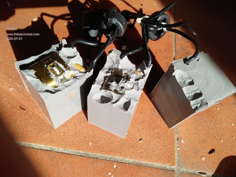
A bit more digging and it appears to have 3 of these. Not sure if the others are the same.
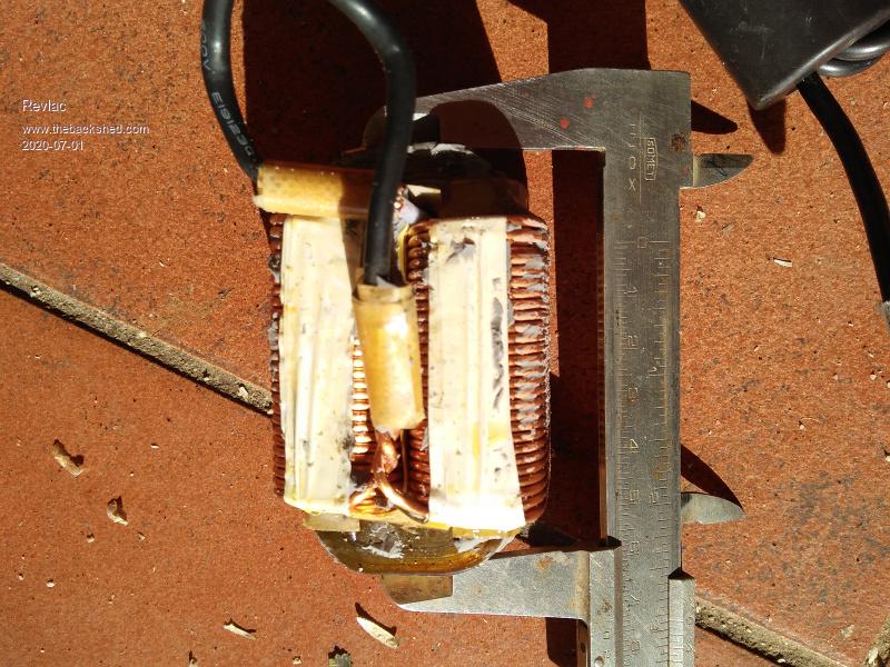
Now its out, it seems to be made of that thin flake silicon steal, the core measurements are 75mm long 30mm deep and 11mm thick core, the wire is about 1.6mm and roughly 26 turns per layer, 3 layers also both winding's seem to be parallel.
There are some other useful parts, a LEM sensor an 2 other CT's
There are likely many other places to find parts. Cheers Aaron Off The Grid
poida Guru Joined: 02/02/2017 Location: AustraliaPosts: 1480
Posted: 08:54am 01 Jul 2020
Copy link to clipboard
Print this post
You are on to it. There is Gold In Them Thar Hills.
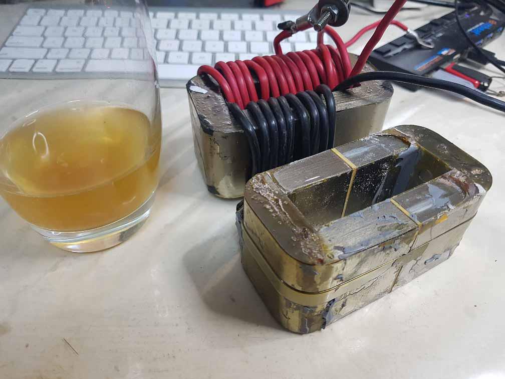
Today I got around to getting the big C core out of a large potted thing I pulled out of one Aerosharp or the other. It was rather like what you had but a bit bigger. I used the 4" angle grinder to remove all copper windings, then belted the inner part out with a hammer and drift. Now I have another one of these: the laminations are paper thin, and that is why they work at these high frequencies (for Si-Iron cores)
These cores are quite good, only need 20 turns for 150uH. No more Henries are needed.wronger than a phone book full of wrong phone numbers
Warpspeed Guru Joined: 09/08/2007 Location: AustraliaPosts: 4406
Posted: 11:10am 01 Jul 2020
Copy link to clipboard
Print this post
That sounds just about right.
Mark used two sets of those cores, with 14 turns of 20mm sq wire (10mm O.D. over the plastic) which had two layers of 7 turns around both sets of cores, which ended up being a bit of a tight fit. That was for his 5Kw pwm inverter choke.
From what I remember, it ended up measuring as 185uH and had about 135 amps saturation with the original air gaps. Edited 2020-07-01 21:15 by WarpspeedCheers, ĀTony.
Revlac Guru Joined: 31/12/2016 Location: AustraliaPosts: 1282
Posted: 12:43pm 01 Jul 2020
Copy link to clipboard
Print this post
Ok, looks like the way to go Peter, I will clean up the other 2 and probably stack 2 together and see what air gap it has already. Some appropriate size wire and should end up with something that will work.
I would have liked to keep the wire, but as its a tight fit, I might do the same and give it the angle grinder treatment to help get it apart.Cheers Aaron Off The Grid
Davo99 Guru Joined: 03/06/2019 Location: AustraliaPosts: 1585
Posted: 11:05pm 01 Jul 2020
Copy link to clipboard
Print this post
I picked up a heap of those blue inverters a while back and kept those choke boxes because they were so heavy I thought there must at least be some copper wire in them.
I still don't really understand Chokes if anyone wanted to impart some knowledge to the ignorant.
Are these things good for anything else? I pulled 3 out of another inverter the other week. These weren't potted just mounted on the casing and are beautifully wound and made. They were in an Aurora inverter of which I also have another 3 of that all have the same fault of a wildly swinging MPPT voltage. They are on a ferrite ring and tightly packed on the winding with a coat of varnish that makes them look very impressive. Obviously just one piece of wire with both ends. Yes, I know I'm a hoarder but they literally looked too nice to throw away or pull apart at least till I found out more about them and if they had any other practical use.
At very least they looked like something I could do a " Free energy " BS Yt vid on and get a Million views in a month from all the fairy dust believers and put a " Don't be suckered by this sh*t" warning at the end. I'm always amazed how many people will watch Vids of a few resistors with some turns of wire and think it's some new miracle discovery Free energy devise that can light a bulb and put comments asking for plans or how much to buy them. Don't understand how so many people can be so Gullible?
So far mainly I have been getting the caps and the fets out of the inverters. Interesting to see how the different ones are built and the components they use. Still waiting to find one with a Big Old toroid.
They seem rare compared to the electronic crap ones that always go out with the dodgy relays.
Revlac Guru Joined: 31/12/2016 Location: AustraliaPosts: 1282
Posted: 02:34am 02 Jul 2020
Copy link to clipboard
Print this post
Davo, can you post a photo of the Aurora inverter ferrite ring? Might see if they have other uses, I do see some Aurora inverters for sale up here occasionally, but not worth what some people are asking.Cheers Aaron Off The Grid
Davo99 Guru Joined: 03/06/2019 Location: AustraliaPosts: 1585
Posted: 08:02am 03 Jul 2020
Copy link to clipboard
Print this post
Sure, I'll try to do them tomorrow for you.
Yeah, I'm constantly bemused at what people want for all things used in solar. I saw someone the other day selling a non working inverter "for parts" for $150. What do they think is in the things, Gold?
I think a lot of people selling solar stuff have the idea in mind that they paid $7K for a system 7-10 years ago and base it's used value on that completely ignoring the fact they just bought a 6.6 Kw system for $4k and still think their old non working 2Kw system is work $1000 and often ask a LOT more.
I was poking around in the shed today and came across a couple of inverter boards I have taken out but not stripped yet. Going to try de soldering them with the H4 Headlight method.
One of the boards has a couple of these smaller and not so tightly wound Chokes on it. Not sure what it was, I think I have only done the one aurora inverter because I wanted the Case for Tonys direct solar Board I was building. I had pulled apart some other inverters I had for the case which was why I didn't strip the boards straight away. Have a whole plastic tub of all other bits and pieces and screws etc I have pulled out.
poida Guru Joined: 02/02/2017 Location: AustraliaPosts: 1480
Posted: 09:49am 03 Jul 2020
Copy link to clipboard
Print this post
Desoldering methods I use:
a 4 inch angle grinder with a metal cutting disk (1mm thick or so) a decent soldering iron that can give a fair bit of heat. (in this case it's a JBC AD 2200 55W thing I got from ebay)
Cut the PCB away from the mainboard in such a way that it includes the part you want but not buggering up the pins or housing of the part you want.
Cut the small PCB cutoff in a way to allow you to heat one pin but leave the other pin still connected. This means you cut the PCB cutoff to have 2 pins only for a small pcb cutoff. Then when you heat one pin, you can move it up and away while only bending the still cold pin and pcb pad. Then you move to the pin and heat it. One pin then the other, one then the other.
I can get anything off a large pcb this way.
The current sensors are the good bits if you can get them but you need to heat all 3 pins (at 0.1 inch pitch) at the same time. This is usually possible. I add a heap of extra solder to bridge all 3 pins and heat the lot then try to pull all 3 pins out.
This work with the grinder removes the high heat conducting paths that are frequently present in power electronics. Edited 2020-07-03 19:52 by poidawronger than a phone book full of wrong phone numbers
Davo99 Guru Joined: 03/06/2019 Location: AustraliaPosts: 1585
Posted: 11:56am 03 Jul 2020
Copy link to clipboard
Print this post
That's a very interesting point. I'm thinking that even cutting the tracks with a dremel would help a lot this way. You could probably get quite close to the pins of most things with one of those little 1" wheels.
I haven't tried cutting the boards but I'll have a look at the next one and see If I think I can manage it successfully. Between the new idea of the light and cutting the board, should make things much easier than I have been doing.
I'm also wondering about grinding the end of the pins where they are soldered might make them be able to be pulled straight out and you'd only loose a MM of pin.
You are right, those sensor coils are mongerals to get free and I have seen some that appear to have extra pins for the sole purpose of just securing them more to the board as they have no tracks going to them at all. They are extra Chunky and overly well soldered making them more impossible to shift.
I use the repeated heat, suck and wiggle method to get big caps off boards. The pins are widely spaced and short and often have a big dob of goop to hold them on even better. Makes me wonder what the designers are thinking the way they mount some of these things. Do they expect the home they are going to be mounted to the walls of will be subject to non stop earthquakes or are they thinking they may be mounted on the side of a rock Crusher?
wiseguy Guru Joined: 21/06/2018 Location: AustraliaPosts: 1297
Posted: 12:01pm 03 Jul 2020
Copy link to clipboard
Print this post
A method I use is a black and decker heat stripper gun. Use it out in the open - downwind as it stinks a bit. Aim at the track side & circle the areas & when you get it hot enough a sharp tap will remove most items lol.
Its a bit agricultural and I wouldn't try to re-use the board but its fast and efficient for recovering parts.
I got my E65 PCB bobbin bits back this week so will make up a EE65 triple stacked core + bobbin and report back how it performs. - Whoops this bit belongs in Poidas thread.... Edited 2020-07-03 22:08 by wiseguyIf at first you dont succeed, I suggest you avoid sky diving.... Cheers Mike
Warpspeed Guru Joined: 09/08/2007 Location: AustraliaPosts: 4406
Posted: 10:22pm 03 Jul 2020
Copy link to clipboard
Print this post
+1 on the hot air gun method.
Sometimes there are only a very few useful parts worth salvaging, and they seem to be the larger parts such as mosfets, relays, large electrolytics and Hall current sensors.
These all have multiple connections onto the board and can be a real bugger to unsolder and remove. Large copper areas and plated through holes do not help either.
So fire up the multi kilowatt hot air gun, point it under the board, and there will be smoke and smell, the board goes brown, but the part just falls off the board. Most of the heat stays under the board, and the component is pretty well shielded from the blast.
As parts come off in seconds, with very little heating of the part, this works quite well. The board itself ends up black and buckled, burned to a smoking ruin, but that does not matter.Cheers, ĀTony.
BenandAmber Guru Joined: 16/02/2019 Location: United StatesPosts: 961
Posted: 10:31pm 03 Jul 2020
Copy link to clipboard
Print this post
I also use the burnt and bubbling board method lolbe warned i am good parrot but Dumber than a box of rocks