
|
|
Forum Index : Electronics : PV Isolation Relay
| Author | Message | ||||
| Solar Mike Guru Joined: 08/02/2015 Location: New ZealandPosts: 1123 |
Whipped this project together for providing a measure of isolation to your charge controller PV panel input. Connect it up to an over-voltage sense relay on your battery bank to disconnect the PV input to a charge controller should its mosfets decide to go short circuit and the uncontrolled charge situation stuff your $20K battery bank. Failure mode for mosfets is short circuit, all it takes is some lightning activity or dodgy Chinese devices to blow them up. We will be using this pcb module on all PV inputs from various panel arrays; initially an adjustable over voltage sense relay across the 50v bank will be used to switch the PV inputs off and sound an alarm. Circuit uses four cheap 30 amp relays with series contacts to provide a voltage disconnect rating, noting that the actual continuous current rating is 20 amps; also approx limit for 4mm^2 PV cable. The circuit is isolated by using a voltage generating driver, just requires 2 to 3 mA to turn on. Relay coils can be wired in series or parallel by links to suit the battery or psu supply, I'm using 24v relays, so 4 in series can work with a 100v battery bank. Its unknown how long these relays would last if switched off at full power, but I don't really care as long as the expensive battery bank is protected with this plan "B" solution. My system at home currently has a 1000v 400 amp vacuum relay, these are several hundred $, bit over the top, so will be replacing it with this setup and use the vacuum relay to disconnect the inverter load if the bank voltage gets too low. Schematic: 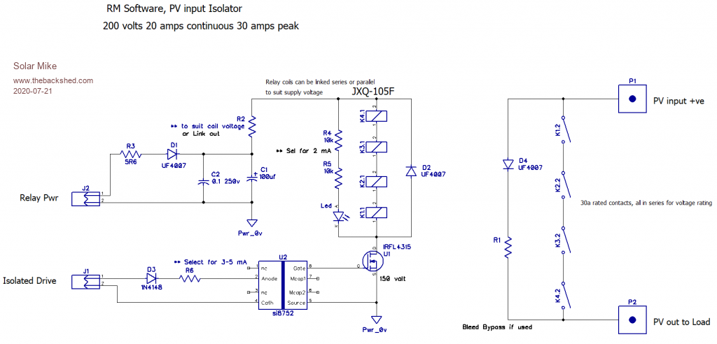 PCB (100x100mm): 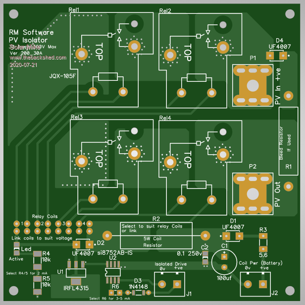 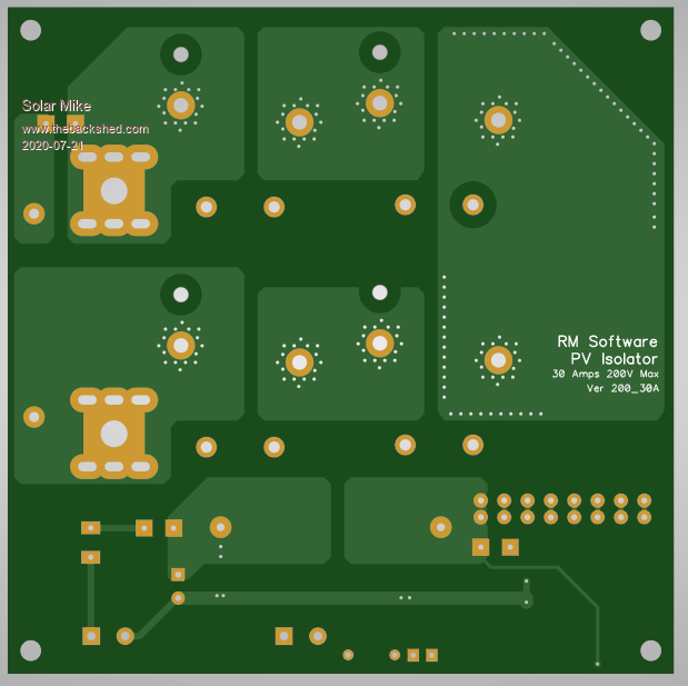 If anyone wants the gerber files, send me a PM. Cheers Mike |
||||
| poida Guru Joined: 02/02/2017 Location: AustraliaPosts: 1388 |
That's right, failure mode for MOSFETS has always been short circuit whenever I've blown them. When they go short circuit, full power from the array goes into the battery with no control so a ruinous overcharge is likely. wronger than a phone book full of wrong phone numbers |
||||
| Warpspeed Guru Joined: 09/08/2007 Location: AustraliaPosts: 4406 |
Agreed, and its very nasty. If this ever happens, battery voltage is going to rise, but not very quickly. The protection (whatever it is) can be fairly leisurely. Tripping a dc circuit breaker with a shunt trip coil is my preferred method. A lower cost way might be a fuse and a crowbar circuit as Peter has already suggested. Cheers, ĀTony. |
||||
| Volhout Guru Joined: 05/03/2018 Location: NetherlandsPosts: 3510 |
I personally have a bad eperience about series connected relay contacts. Mechanical relays have different closing and opening times. Putting contacts in series without any balancing or protection will destroy the slowest relay in no time. I would choose a suitable relay (even if it is a big one). Volhout PicomiteVGA PETSCII ROBOTS |
||||
| Davo99 Guru Joined: 03/06/2019 Location: AustraliaPosts: 1577 |
I don't think that matters. This is a fail safe. As pointed out, If you fry a say $4 relay ( or several) and save a large battery bank, who cares? This is only protection when something else has gone arse up so it's not like it is going to need to be switched every day. Perhaps a circuit that monitored voltage and could be used to trip an alarm of an over or under voltage would also be useful in this situation. |
||||
| Solar Mike Guru Joined: 08/02/2015 Location: New ZealandPosts: 1123 |
Agree, doubt if all 4 relays will open at the same time, will be close though as they are on the same circuit. A suitable single relay costs > $200, as apposed to $10 for 4 of these cheap ones, it will only operate if battery volts exceed a high set point eg PV charger has failed short cct, so may never trip. Personally I have never had this happen, none have failed, always a first time though. As we require 4-5 of these, I cannot justify paying over a grand for vacuum relays that may never be used, will just keeps some spares in the parts cupboard in case they blow up. Looked at shunt trip coils, need 5, they cost approx $250 each here in NZ, so that option is too expensive also. Cheers Mike |
||||
| Warpspeed Guru Joined: 09/08/2007 Location: AustraliaPosts: 4406 |
Keep a beady eye out on e-bay. Brand new Chinese shunt trip coils often go for about thirty to forty dollars. There are some there now for thirty three dollars, but the trip coils appear to be 230v ac which is pretty useless for us. https://www.ebay.com.au/itm/Shunt-Trip-Auxiliary-Contact-Add-On-Module/222813519305?hash=item33e0b87dc9:g:9jgAAOSwoBlabSIl Cheers, ĀTony. |
||||
