
|
|
Forum Index : Electronics : Influence current and voltage ripple on a battery
| Author | Message | ||||
| nickskethisniks Guru Joined: 17/10/2017 Location: BelgiumPosts: 462 |
Hi girls and boys, I think I found a new (interesting?) subject to discuss. �  So, during my inspection rounds, I discovered something I already knew before. I was measuring an AC ripple current in my DC system! �What? I already knew because I was heaving troubles before when reading some current LEM in my �C and monitor system. I�m not going to explain, I found a small paper of Victron that explains it verry basically. link I know ripple current is bad when charging a battery, well the ripple voltage that goes with it, is bad, because suddenly your charging voltage is not constant. And the ripple voltage is overcharging your battery. �Probably not a big issue when charging with a switched mode supply, the ripple voltage will probably be very little with those supplies. For example yesterday, I was measuring. My inverter was delivering about 1500W and it was completely powered by my solar panels. My batteries were taking 1.5A @ 55.6V, but when reading the AC current with a true rms meter, I got a reading of 22.5A! I was not expecting that at all! So going a step further, when my inverter was delivering 7500W I measured about 100A going out of my battery the rest was fed by the solar panels. Now, when measuring the current with my true rms current clamp it was about 94A AC! I know I can�t really trust my meter, I need to use a lem/shunt with scoop meter on in to monitor and measure it correctly, but still it would proof something right? So when googling about this behavior I couldn�t find a lot of information about it, I read some papers, (impact of current ripple on li-ion battery aging for example). link But not much on lead acid batteries. I think I can conclude that if your battery is big enough it�s not a great deal for your battery. For the caps in the inverter itself it�s of great importance to use capacitors that are rated for the job. And place your battery as close as possible to your load. So that�s something I need to redo, or adding more capacitors close to my inverter, to lower the stress on the inverter capacitor bank. So what I actually want to know, how much ripple current can we tolerate in our system/battery? And if I want to correct it somewhat, how do I calculate an LC (LCL filter?). Edited 2020-07-30 23:48 by nickskethisniks |
||||
| Pete Locke Senior Member Joined: 26/06/2013 Location: New ZealandPosts: 182 |
What was the AC voltage measured at the batteries, and what frequency? Cheers Pete'. |
||||
| noneyabussiness Guru Joined: 31/07/2017 Location: AustraliaPosts: 526 |
I think you hit the nail on the head, lead acid batteries are very tough and tolerant of small over charges... as long as water and temp are kept within tolerance... there are some schools of thought that ripple is good as the higher voltage, low power spikes can help desulphation.. Inverter if set up correctly should be able to handle modest voltage spikes, however must have adequate capacity... personally my VERY conservative rated 5kw inverter has roughly 120000uf 80v's on input... I think it works !! |
||||
| poida Guru Joined: 02/02/2017 Location: AustraliaPosts: 1432 |
Just so we can have some picture of what's happening, here is the test inverter. 6 x 3,900uF on input. Probably not enough. 4 MOSFETs, one per leg. 50.9V DC input 240V AV output @ 50Hz 400 W AC RMS resistive load current sensor is 0.207V / Amp and placed at the DC supply positive lead's terminal Below is the input voltage, AC coupled to permit 1V/div, Yellow and the input current, 4.8A/div, Purple and the 50Hz trigger source in Light Blue 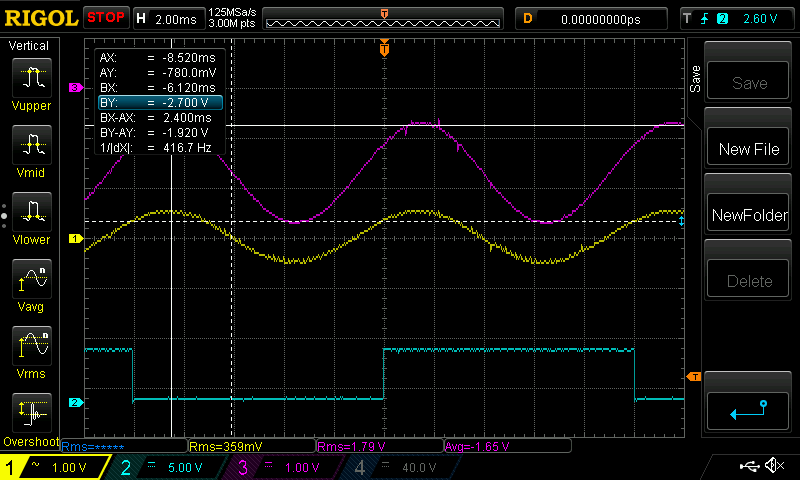 We can see the DC current remains negative throughout the 50Hz cycle. The input voltage has also an AC component. This input is AC coupled so there is probably a DC offset which we will not see, lower than nominal supply voltage, when running this load. The cursor shows the current ripple, 1.92V p/p. This is 9.2A peak to peak ripple current in the DC supply. The DSO calculates RMS current as 1.79V or 8.6A RMS. This includes the DC offset we can see. It also looks at the Average value, which is not RMS. This average is lower. I put the Fluke 87 in circuit with the DC supply. The 87 can do AC RMS on both V and I. It shows 8.4A DC current and it shows 3.2A AC current The Uni-T DC clampmeter is not too bad, it gave me 8.43A DC and 3.2A AC, the same as the Fluke. 9.2A p/p current ripple with a 400W load and 6 x 3,900uF DC capacitance. I took the 6kW Mad power board out of the spare inverter. It has 5 x 10,000uF caps. It has 12 MOSFETs, not just the 4 fitted to the above test inverter. Let's see the difference if any, from a 2x capacitance increase. 50.2V DC input Same as above for everything else. 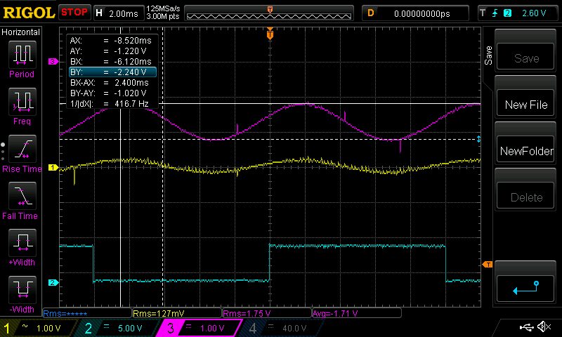 The DSO says 1.75V RMS input current, which is 8.45A RMS Fluke shows 8.44A DC and 1.7A AC Ripple current is a lot less now. 4.9A peak to peak ripple current. Double the capacitance seems to halve the ripple. This is at 400W. I think there will be large ripple current present no matter how much capacitance you use, when driving multi kW loads. The ripple current is proportional to output power as well? The efficiency of the 6kW Mad board is quite good. 1.75 / 0.207 = 8.45A RMS input, at 50.3V DC = 425W input Output is 400W, efficiency is 94.1%. Not too bad. Edited 2020-07-31 16:26 by poida wronger than a phone book full of wrong phone numbers |
||||
| Solar Mike Guru Joined: 08/02/2015 Location: New ZealandPosts: 1162 |
I would have thought the ripple current (ergo ac voltage) as seen by the battery, when measured at the battery terminals, would be determined by the battery internal resistance. Last time I checked my battery pack had an internal R of < 0.2mR; so any ripple say at 100 amps would be 0.0002 x 100 = 20 mV; that's not going to affect anything. Voltage drops in the external cables, fuses, breakers reflect into your equipment as AC ripple and would normally be much higher than that experienced by the battery. Cheers Mike |
||||
| nickskethisniks Guru Joined: 17/10/2017 Location: BelgiumPosts: 462 |
Thank you all for the input. I did some scoop testing today, and I don't need to be concerned about my battery, it's to big to measure the impedance. I couldn't find a ripple higher then 20mV.I need to test individual batteries to do it properly. What I need to be concerned about is the voltage ripple in my system. When loading with around 4500W (51V) I got 2.6V 100hz ripple on my solar controller output... And that's not even at the input of my inverter... I need to take some actions to improve the stability of the system, because I'm impressed about the fact it's still running after more then 4500kWh. Biggest problem for sure, I do have long 25mm^2 cables running to my battery. So to long and underdimensioned. I will post some scoop images after I examined them closer. Edited 2020-08-01 00:09 by nickskethisniks |
||||
| nickskethisniks Guru Joined: 17/10/2017 Location: BelgiumPosts: 462 |
I was allways thinking there should be some kind of DC offset but there isn't... It's a DC sinewave, and I can't talk about ripple current can I? Underneath the signal of my has200-s current sensor, 1V = 50A. The load was around 4500W on AC side with 2 resistive heaters and some led TL lighting and fans. So about 120A peak on DC side, the reading is a little bit of, in reality a bit more I think. ( The charge controller off) 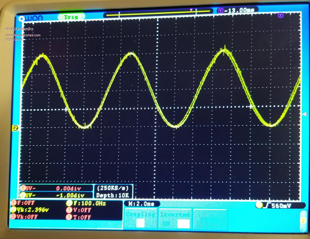 This is the output voltage (AC ripple)of my solar controller (buck topology) it was outputting 45A. And there was 4500W of load in the system. About 2.6V voltage ripple. 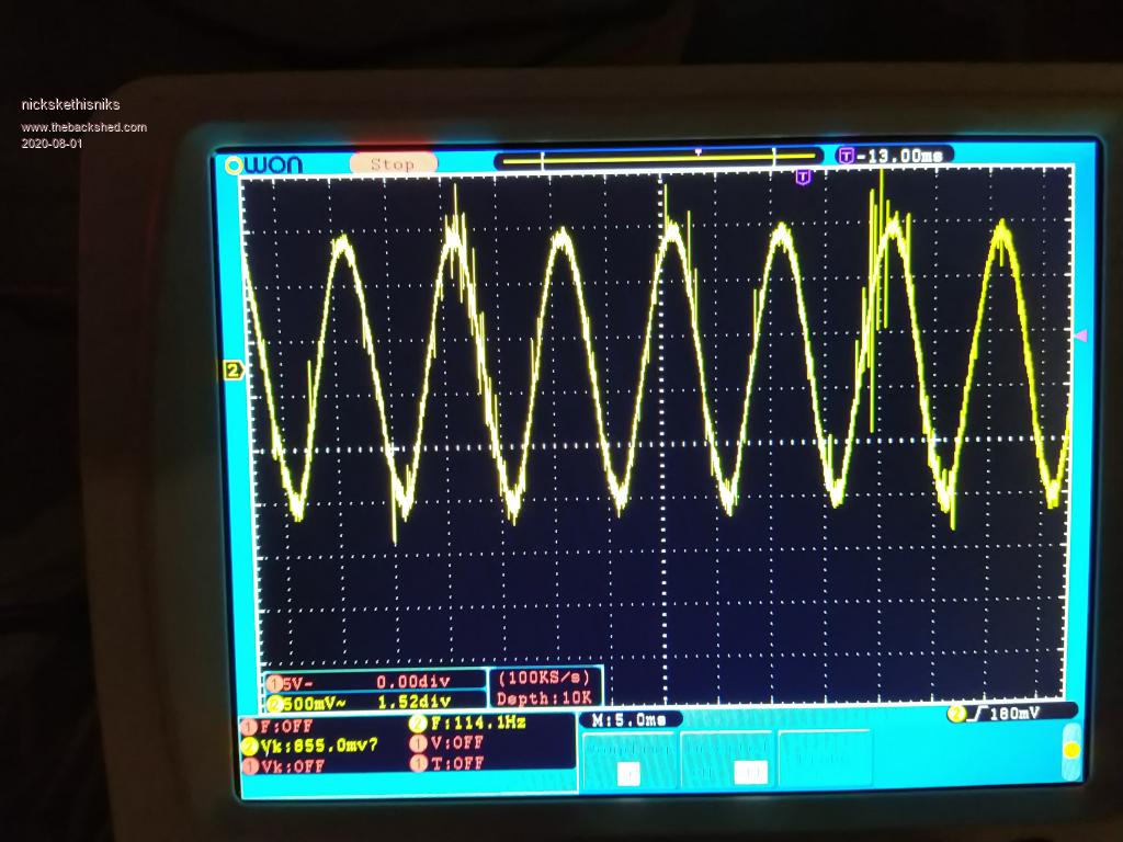 This is the output current, and that's the most interesting image I guess. I think charge controller was putting out less then 45A At that time. We have a DC offset and hugh ripple current. 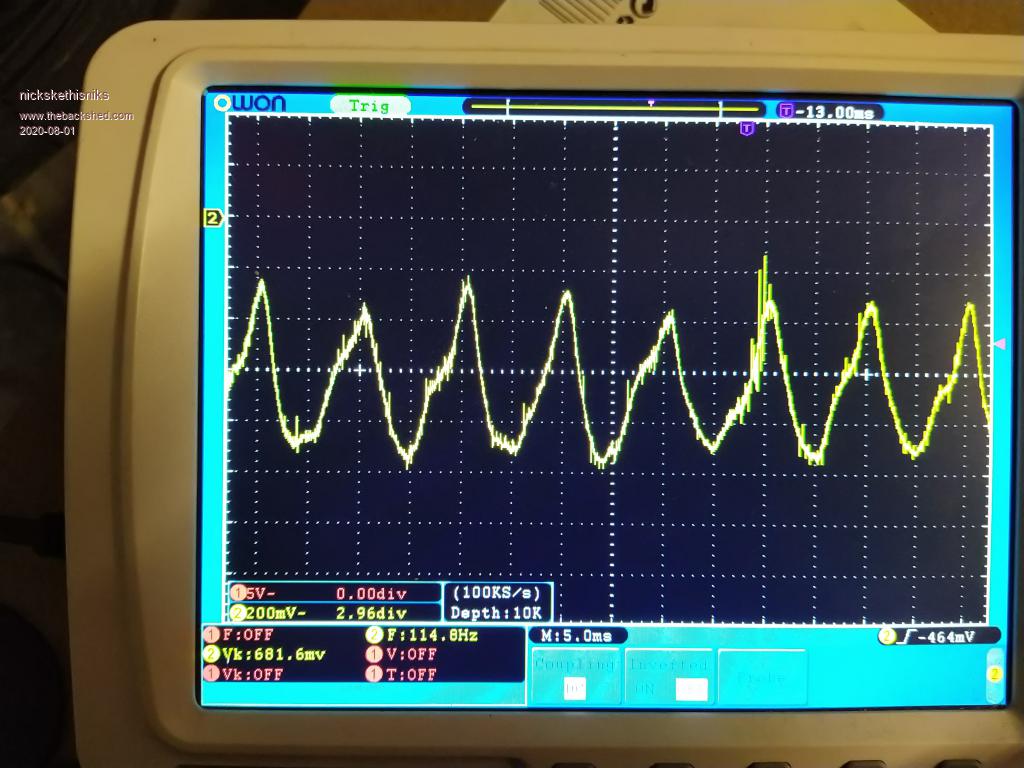 This image shows me I need to make some changes to my system. Cause I think my charge controller is probably struggling and having a hard time. Edited 2020-08-01 07:10 by nickskethisniks |
||||
| poida Guru Joined: 02/02/2017 Location: AustraliaPosts: 1432 |
Yes, exactly right. I wanted to see the difference between some and 2x some capacitance, to get a feel for it. The basic circuit, of battery, breakers, fuses & cables etc all in series means they all experience the same current ripple. wronger than a phone book full of wrong phone numbers |
||||
| poida Guru Joined: 02/02/2017 Location: AustraliaPosts: 1432 |
Nicks, I think what you are seeing, when looking at the charge controller's battery connection is the CC output voltage is closely following the battery voltage, which is being pulled up and down by the inverter. the CC control system (basically constant voltage closed loop) does not need to follow the 100Hz, it will give excellent results if it can follow battery changes of the order of 2-10 seconds or slower. The CC current waveform is sort of what I would expect it to be too. The 100Hz load of the inverter, placed on the battery alters the battery resistance a bit, depending on the current draw and the battery voltage. As a battery gets more charged, it's resistance increases ( I discuss lead acid battery only). So the peak current draw from the inverter will bring Bv down, and while it is down, internal resistance reduces, becoming a lesser resistance load to the dc-dc converter of the charge controller. And the CC has not altered pwm width yet so it's output current increases as it's load resistance (battery resisitance) drops. Then the inverter requires less power (1/2 a 100Hz cycle later) and the opposite happens. less Bat IR, less load on dc-dc converter output, so Bv goes up for 2 reasons. wronger than a phone book full of wrong phone numbers |
||||
| The Back Shed's forum code is written, and hosted, in Australia. | © JAQ Software 2025 |
