
|
|
Forum Index : Electronics : Help for current control
| Author | Message | ||||
| stevebequik Newbie Joined: 20/07/2016 Location: AustraliaPosts: 12 |
This is a little off topic, but there are obviously some very clever clogs on the forum so here goes, I have built a couple of e dirt bikes for myself and my son. Based on a KTM 250 and a KTM 65. The full-size bike has a 21s2p 54ah 4.2kwh battery using Chevy volt gen 2 pouch cells, The mini has a 18s1p 15ah 1kwh battery using Chevy volt gen 1 cells. On longer rides, the mini runs out of juice while my bike has heaps of spare capacity. So thinking a small device I can carry in the back pack to connect the two batteryÆs while we take a break. As the big bike is 21s and the mini is 18s, I want to build a very simple buck converter to limit current to around 15amps. Voltage regulator/cutout is not required as we will be monitoring voltage and stopping well before battery is full. Typically around 84v volts in and 70v out, so 100v components. IÆm a sparkle, with some Arduino experience, can follow instructions and happy for a few bangs, but need some direction. Electric dirt bikes work amazingly well. I believe itÆs a major conspiracy that the majors are not all over this. So if anyone is interested, happy to answer any questions. So , any ideas on the simplest, smallest way to achieve this. Thanks |
||||
| nickskethisniks Guru Joined: 17/10/2017 Location: BelgiumPosts: 462 |
You would like to build it yourself? The easiest way is to use a resistor, and a relay to disconnect when end voltage is reached. But I think you would want to use a buck converter to maximize efficiency, I would suggest to use a current mode pwm controller like UC3843, so you have current limit and voltage limitation. You will need a small dc converter to convert your (high) battery voltage to 12 or 15VDC to power the ic, you will need a gate driver like TLP250 of FOD3182 to drive an N-channel mosfet. Because the mosfet will need to be in the V+ line. Therefore you will need an isolated dcdc converter as well. Ā You can read the solar MPPT controller topic for guidance on a high power buck converter and make a smaller version. As you want to charge a battery you will need to have cycle by cycle current limit, so it's difficult to implement it in a ĄC, not impossible though. But I think a dedicated pwm ic is more suitable for this, for safety reasons you will need an extra diode in series with your output. This is just for principle, schematic is not complete and values are not correct: 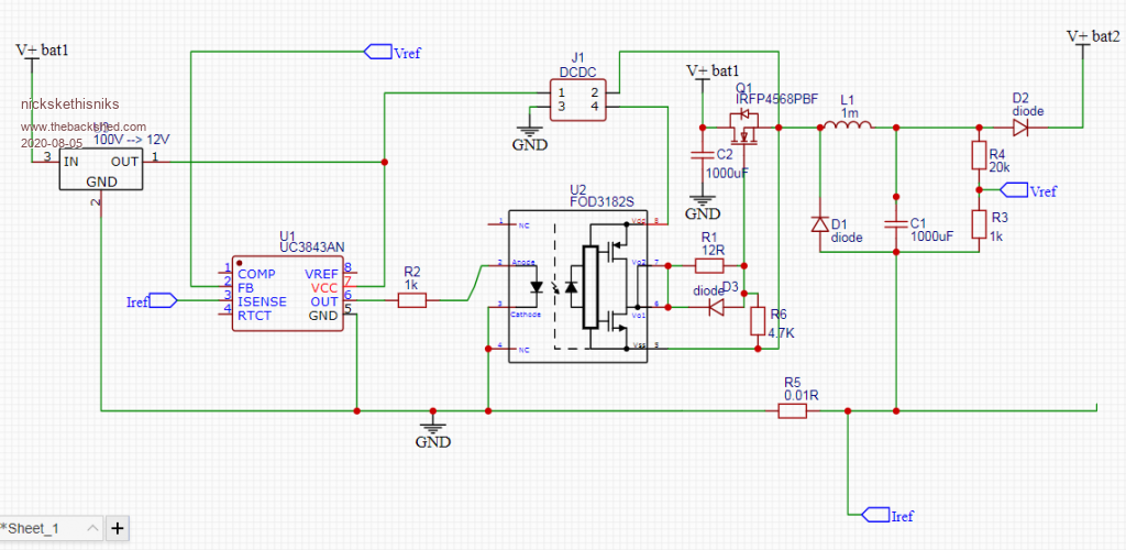 I'm not confident about the current measurement, it's possible it needs to be measured before the mosfet. But there are solutions for that. I hope this is a good startingpoint for you. Edited 2020-08-05 20:29 by nickskethisniks |
||||
| stevebequik Newbie Joined: 20/07/2016 Location: AustraliaPosts: 12 |
Hi Nick, Thankyou for taking the time with your detailed response. Gives me a great start and direction with research and data sheets. I am a little confused with the second DC-DC converter and why itÆs required. Like I said, trying to make this as simple as possible. So need to get my head around that. Would be great if it wasnÆt required. Thanks. |
||||
| nickskethisniks Guru Joined: 17/10/2017 Location: BelgiumPosts: 462 |
You can drop it if you put the MOSFET in the negative side, then you can drop the optomosfetdriver also. And drive the MOSFET directly from the IC. But then you can't measure output voltage on a simple way, you need to figure out how to measure that if you want to have voltage regulation. (or not). I think you can achieve that with an optocoupler. |
||||
| Warpspeed Guru Joined: 09/08/2007 Location: AustraliaPosts: 4406 |
I would go about all this a little differently. A buck regulator is fine, but I would use direct current measurement of the second battery to switch the thing on an off. The basic concept would be a pair of jumper cables between the two batteries, and assume some kind of safe current limit, say ten amps (for the sake of this example). If the current is less than ten amps in the battery being charged when initially connected up, turn the mosfet hard on and leave it on. If/when the charging current ramps up to the ten amp maximum (through the inductor), switch the mosfet off when it reaches ten amps. And turn it back on at say eight or nine amps. The mosfet may oscillate on and off initially, and eventually stay switched on when the charging current falls below the ten amp maximum peak required to turn it off. I would expect the thing to oscillate on and off for a brief interval at initial connection, then stay continuously on. Cheers, ĀTony. |
||||
| nickskethisniks Guru Joined: 17/10/2017 Location: BelgiumPosts: 462 |
But you would still need some kind of comparator/opamp circuit with a mosfetdriver? Something more like this? 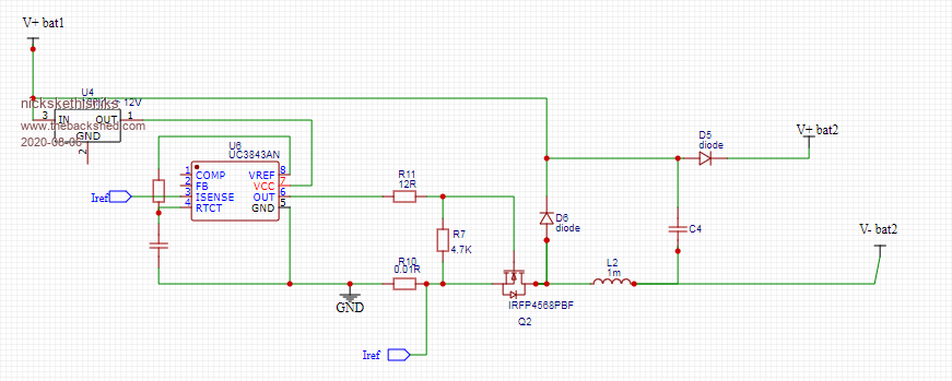 |
||||
| Warpspeed Guru Joined: 09/08/2007 Location: AustraliaPosts: 4406 |
That comes pretty close, 8.4v undervoltage lockout, 100% duty cycle, all good. Pin 2 voltage feedback would need to be grounded to produce the maximum 100% duty cycle. Problem though with I sense. Ā That needs to go up to one volt, and a current shunt that generates 1v is not practical. A single supply rail five volt Hall current sensor powered from v ref should work though. Set that up to provide one volt output at ten amps (or whatever) and you should be in business. The UC3843 works up to +30v supply, so the twelve volt regulator is not really required. A nice circuit with very few parts. Data sheet: https://pdf1.alldatasheet.com/datasheet-pdf/view/29378/TI/UC3843.html Edited 2020-08-06 19:41 by Warpspeed Cheers, ĀTony. |
||||
| nickskethisniks Guru Joined: 17/10/2017 Location: BelgiumPosts: 462 |
The UC3843 is just a suggestion feel free to use whatever you want. There are probably other IC's, for current sensor you can use the acs712-30. Or a small shunt resistor and opamp amplifier, lm258 for example. |
||||
| poida Guru Joined: 02/02/2017 Location: AustraliaPosts: 1432 |
maybe use the INA168 current sense amp here. It can be placed on either low or high side of the output across the shunt resistor. wronger than a phone book full of wrong phone numbers |
||||
| Warpspeed Guru Joined: 09/08/2007 Location: AustraliaPosts: 4406 |
Excellent suggestion Cheers, ĀTony. |
||||
| wiseguy Guru Joined: 21/06/2018 Location: AustraliaPosts: 1210 |
A cheap & simple fix is just to add a 0.9V offset to the I sense feedback signal. When the upper variable resistance is trimmed to ~66R (2266 ohms total) the current through the 0R01 is ~ 10A. 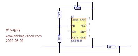 Edited 2020-08-09 14:07 by wiseguy If at first you dont succeed, I suggest you avoid sky diving.... Cheers Mike |
||||
| stevebequik Newbie Joined: 20/07/2016 Location: AustraliaPosts: 12 |
I have gone ahead and ordered a few UC3843 f IRFP4568 to have a play. Thanks to everyone for your input. Warpspeed, you mention the 12v regulator is not really required. Are you implying I could get away with a simple voltage divider instead? Wiseguy, your idea looks good to me, but what happens to the Isence input? Thanks Steve |
||||
| Warpspeed Guru Joined: 09/08/2007 Location: AustraliaPosts: 4406 |
Steve, If you read the data sheet for the UC3843 it can work DIRECTLY from a dc input of up to +30v. Cheers, ĀTony. |
||||
| wiseguy Guru Joined: 21/06/2018 Location: AustraliaPosts: 1210 |
Hi Steve, Whoops my mistake, the tapping of the two resistors should have gone to the current sense feedback (Isns) not voltage feedback. The FB could be connected to Gnd as per Warps suggestion or used to set the max Charging voltage via an isolated sense scheme. A few words on what is happening inside the IC might be helpful. When the FB pin is higher than the internal 2.5V reference the PWM is truncated each cycle until the FB = 2.5V. ĀWhen the Isns is greater than 1V the FET drive output is truncated until the next cycle. The data sheet is misleading with regard to VFB & VRef, see data sheet Pge14 says about Vref (5V) "VREF is the voltage reference for the error amplifier" which is crap, if you look at the internal schematic 2 pages earlier it shows the error amplifier is internally connected to 1/2 Vref (2.5V). When I previously wrote 5V for F/B it did not look right hence this edit. Perhaps it might be wise to use some method of checking the smaller battery terminal voltage and either automatically stopping the converter or at least triggering a buzzer or alarm to stop the charging. My thoughts on how to power it all is to use one of the small $2-3 mains to 12V or (15V) converters such as here . Although I haven't used one of these ICs in a current only controlled manner the scheme should work ok. ĀIf you want to control the max output voltage in my experience it is better to ground the FB pin and use an optocoupler, collector direct to the comp pin and emitter to ground. The LED side should be powered & driven from another little power supply 110/240 to 12V, (or a 12V to 12V isolated 1W unit like this Āpower from the main batt 12V supply) use the 12V and a TL431 with suitable resistors to sense the smaller Batt volts & drive the LED. ĀThe comp pin will usually require a (100n typically) capacitor to ground for stability. If you need further diagram help just ask but I dont believe in having all the fun, have a go yourself first. Whilst the Uc3843 will operate at up to 30V keeping the gate drive around the 12V mark will provide best results & I assume you want to use the ~80V source battery to power up and run this device ? ĀThe small power supplies will work fine usually from about 35V up typically. ĀIf you order from Aliexpress I hope you're not in a great hurry.... Edited 2020-08-16 11:03 by wiseguy If at first you dont succeed, I suggest you avoid sky diving.... Cheers Mike |
||||
| The Back Shed's forum code is written, and hosted, in Australia. | © JAQ Software 2025 |
