Notice. New forum software under development. It's going to miss a few functions and look a bit ugly for a while, but I'm working on it full time now as the old forum was too unstable. Couple days, all good. If you notice any issues, please contact me.
Solar Mike Guru Joined: 08/02/2015 Location: New ZealandPosts: 1228
Posted: 12:13pm 02 Sep 2020
Copy link to clipboard
Print this post
I have a requirement for a simple 4 battery cell BMS plus integrated mppt charge controller, this post is to record the design and testing.
After rescuing a number of very old Lifepo4 40AH battery cells; approx 36 in total, discharging and recharging a couple of cycles using the Cell-Pro 8 to accurately access their condition, several are duds with only 6 to 10 AH capacity, the remaining all seem to be in the 18 to 22 AH range or about 50% capacity, so they are still useful but definitely on the way out.
Intention is to make up some stand alone 4 cell 12 volt battery sets to be used to run some solenoid valves, small pumps, controllers etc out in the field away from the main battery bank; each 12v battery will have a 100w PV panel as power source. These batteries are not matched in any way and will require a simple BMS system to keep them TOP balanced. Charging 4 in series even to say 3.47 volts each, some will charge up first and exceed the 3.6v limit, if I zap the high ones with a 1 amp load, they all reach the same end point reasonably quickly.
The other BMS design is way over-kill for this project, I will only ever need 4 cells, so expand-ability isn't a requirement. I looked around for off the shelf low cost BMS units, but all are designed for Lipo's with their higher 4.2v end point voltages, the few I did find advertised as suitable for Lifepo4's were all still too high really and not adjustable. Couldn't locate a charger with multi-cell BMS anywhere, so it's DIY time again.
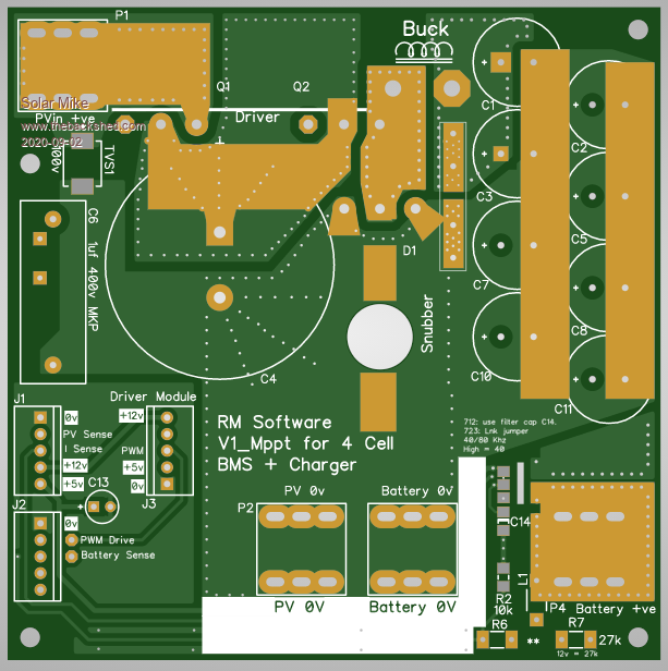
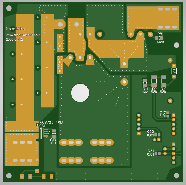
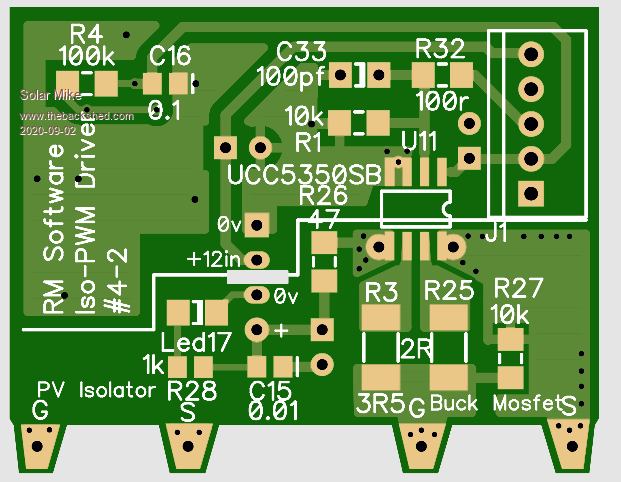
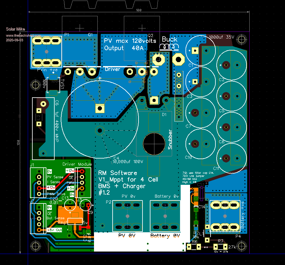
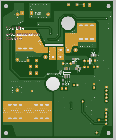
This somewhat modular design has a 4 cell input with cell hopping common voltmeter to measure and apply loads to various cells as required; that is built on one pcb. The other PCB that connects to the BMS unit measures 100 x 100mm and contains the mppt charge controller. Basic design spec for this is up to 100v input and 12v out at 20 - 30 amps max, figured the mppt unit may be useful for other projects, can make it work in non mppt mode by leaving off the electro's and bypassing the inductor if say an 18v pv panel was used. Its pretty difficult to make a small compact mppt charger board having an optimum layout, so have added a small daughter board that contains the driver part, leaving the large current carrying traces optimized on the main board.
Here's the progress so far for the Mppt bit, no circuit as yet, its been designed direct to pcb layout, will create a schematic to check later. The 2 mosfets and schottky rectifier mount under the pcb on the alloy case.
Driver:
Still working on the BMS part.
Cheers Mike
Solar Mike Guru Joined: 08/02/2015 Location: New ZealandPosts: 1228
Posted: 12:01pm 03 Sep 2020
Copy link to clipboard
Print this post
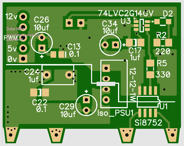
Few changes made to the Mppt power board:
Added a 5 volt regulator rather than pass it in from the BMS controller.
Added an active low, PWM Output drive enable input, the mosfet driver chip has this input, so have passed it through to the input connector, can be used to shut down the drive on over current by using a fast comparator, external to the CPU control.
Increased the high voltage track spacing to 1.4mm, so input\output voltages up to 120 or so can be used, daughter driver board also has increased spacing.
Cad Layout:
Cheers Mike
Solar Mike Guru Joined: 08/02/2015 Location: New ZealandPosts: 1228
Posted: 03:11am 04 Sep 2020
Copy link to clipboard
Print this post
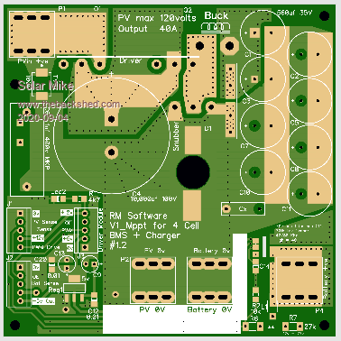
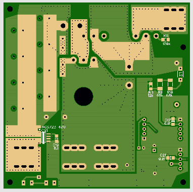
Full size 100x100 PCB: Using 1oz copper 30 amps will be ok, if tinned area's are solder blobbed, no reason why 40 amps would work fine without over heating; each of the small output caps have a current rating of approx 2 amps, so @40A max output and 20% ripple of 8 amps, in theory only 4 caps are required, see how it goes in testing.
Mike
Solar Mike Guru Joined: 08/02/2015 Location: New ZealandPosts: 1228
Posted: 10:57am 05 Sep 2020
Copy link to clipboard
Print this post
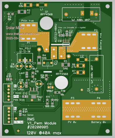
With a copy and paste + few mods a PWM variant is done also; some of the PV panels are a pretty good match to the battery voltage, so mppt isn't worth the extra expense. The PWM version is a little smaller 100 x 82.
Will complete the BMS part now that I know what the charger looks like.
Edit: I also have a 12V @400AH 4 cell Lifepo4 battery that runs a small 12V-230 vac inverter, this runs a fridge and an upright freezer in the garage and a PC in the office as a standalone setup; so I will use this small BMS to make sure those 4 cells track each other.
Currently approx once a year I have to manually re-balance them, there is a bms fitted but it doesn't draw enough load balancing current to do the job effectively. There are a somewhat adhoc mixture of PV feeding the existing charger, hopefully I can switch them over to multiple paralleled mppt modules attached to the new BMS to get a higher charge current, the battery is fine for any currents up to 1C or 400amps.
Mike Edited 2020-09-05 22:02 by Solar Mike
Revlac Guru Joined: 31/12/2016 Location: AustraliaPosts: 1282
Posted: 12:31pm 05 Sep 2020
Copy link to clipboard
Print this post
looks great Mike, Much easier to look after 4 single cells than a lot parallel. Can the 1 amp load be changed if necessary?
I have used at least 3 amp at times, the scenario being low battery from days of cloud, then sunny from midday onward, this usually needs me to take action, be the referee and sort it out before things get out of hand. The rest of the time its quite happy. A change in resistance (another variable) some time later might change things too.Cheers Aaron Off The Grid
Solar Mike Guru Joined: 08/02/2015 Location: New ZealandPosts: 1228
Posted: 04:04am 06 Sep 2020
Copy link to clipboard
Print this post
Easily changed, currently uses a 3R3 ceramic resistor as load, for the bigger cells I will go for a smaller value that bolts direct to the alloy case for heat sinking. The mosfet doing the switching is 18 amp rated.
Note circuit can also be used for higher voltage batteries by altering some resistors.
Mike
Solar Mike Guru Joined: 08/02/2015 Location: New ZealandPosts: 1228
Posted: 12:48am 12 Sep 2020
Copy link to clipboard
Print this post
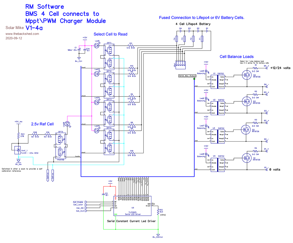
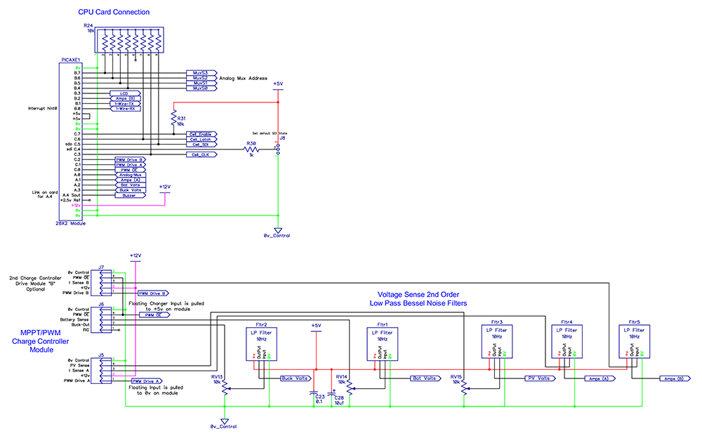
Finally completed 1st cut of the 4 cell BMS + charger, here is the design, for this project I did everything backwards and designed the pcb boards on the fly with the schematic in my head, then drew the schematic from the pcb layout.
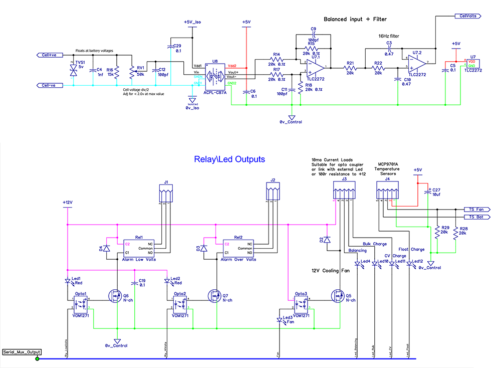
The basic BMS connects to 4 battery cells, voltage anywhere from 1.2 to 12 volts, using a flying voltmeter concept switched across the cells and isolated measurements via an isolation amp that accepts up to 2 volts input.
Optimos switches driven by a serial LED constant current driver select each cell to be measured, self calibration is achieved by switching in a 2.495V reference. The same LED driver also turns on individual cell loads for balancing; the loads are turned off when voltage measurements made.
Isolation amp feeds a balanced to unbalanced buffer amp followed by a 2nd order 12 db\octave low pass filter to reduce noise. Serial LED driver outputs not used for cell measurement or loads are used here to drive a couple of relays and LED status indicators.
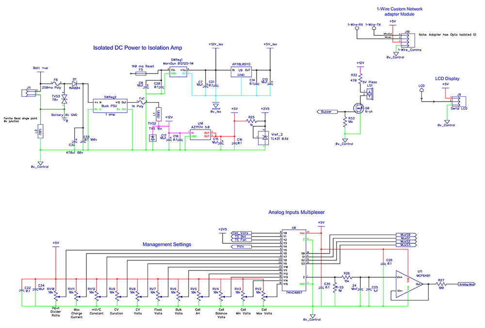
Here an analog multiplexer is used to select various voltage references that control the program set-points, bunch of 10 turn pots used here rather than a software menu system to set everything up, whether this is a good idea or not remains to be seen.
The faster dynamic voltage and current measurements are filtered as necessary and fed straight to the CPU; Picaxe 28X2 used here to make use of 64 MHz speed and interrupts. I have made provision to drive 2 mppt or pwm PV charger modules on separate phases. CPU is mounted on a small 30pin vertical plugin pcb card, I will replace this at some stage with one of the "Mites"; again how well it goes concurrently controlling the BMS and a mppt charger remains to be seen.
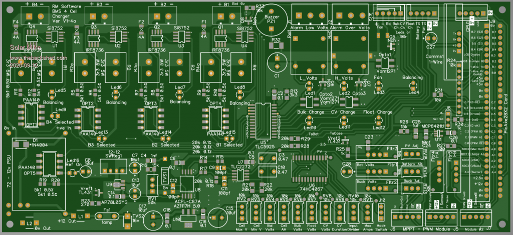
PCBS next.
Cheers Mike Edited 2020-09-12 12:23 by Solar Mike
Solar Mike Guru Joined: 08/02/2015 Location: New ZealandPosts: 1228