
|
|
Forum Index : Electronics : Transformer choice for 300V Warpverter
| Page 1 of 2 |
|||||
| Author | Message | ||||
Haxby Guru Joined: 07/07/2008 Location: AustraliaPosts: 426 |
Hi all, The Prius inverter in my other forum thread is going well. Nearly finished! Just waiting on some bits from China. Now I'm thinking of building another warpverter to suit a full EV battery pack for a nice large power storage solution. The two more popular electric vehicles; the Leaf and the model X both use 96 cells in series for around 360V nominal. And the leaf packs are coming down in price, and the model 3's should start coming through the salvage auctions as people start crashing them, so I am thinking of a 300 to 400V DC input into the next warpverter. When it comes to transformer selection, I like the idea of using unmodified Aero-sharp transformers, or more precisely, slightly modified transformers. Now the aerosharp 1.5kva transformer, UNMODIFIED, is 93V:230V Now bear with me here: For the large inverter; I'm considering taking TWO of these 1.5kva transformers and unwinding some of the 93V side, which is easy to do, to make them closer to 86.6V EACH, then connecting them in SERIES to make the LARGE transformer for the first inverter.... For the medium inverter; Then taking another 1.5KVA transformer and unwinding quite a bit of the 93V winding to make 57.5V, which will make my MEDIUM inverter. Then working out the small and tiny transformers at a later date.... My question is: Can I apply up to 400V max to the 230V AC winding of these transformers? Or will they go bang? And more generally, what is it in a transformer that dictates how many windings should go on the core? I'm not talking about the ratio, but rather the minimum amount of turns for the voltage required. Is there a rule of thumb or is it quite complicated? |
||||
| Warpspeed Guru Joined: 09/08/2007 Location: AustraliaPosts: 4406 |
A simple practical way to tie all this together would be with one of the on line flux calculators such as this one : https://daycounter.com/Calculators/Max-Flux-Density-Calculator.phtml Vrms might be for example 200v F = frequency, 50Hz would be .00005 Mhz N = number of turns ??? Ac = cross sectional area of magnetic core in square Cm. Just ignore the Dc terms. Try to aim for a result of roughly about 10,000 Gauss for each of your Warpverter transformers. Now suppose you wish for a winding for a 200 volt peak square wave. And the frequency is 50Hz or .00005Mhz. But you don't know the required turns ??? The toroid is 6cm high and 4cm wide = 24 sq Cm. (maybe 180mm O.D. with 100mm hole) First try guessing the turns say 300. Plug in the numbers and press calculate. Result 12,512 Gauss. A bit of trial and error and 375 turns gives a 10,010 Gauss result which would be perfect for a 200v square wave (400v peak to peak) winding on either primary or secondary. The flux density is not that critical but if you design each of your Warpverter transformers to work at 50Hz and roughly 10,000 Gauss, and call all the square wave voltages RMS, all four transformers will work very well in this application. Edited 2020-09-05 19:46 by Warpspeed Cheers, Tony. |
||||
mason Regular Member Joined: 07/11/2015 Location: CanadaPosts: 86 |
Hi Warp, just wondering if there's a poor mans way of tuning a transformer, I don't have a function generator all's I have is a scope Thanks |
||||
| Warpspeed Guru Joined: 09/08/2007 Location: AustraliaPosts: 4406 |
Mason, if this is for a Warpverter none of the four transformers require any tuning capacitors or choke. More likely you are building a high frequency Oz type pwm inverter, the transformer will be much better behaved if its correctly tuned to 90 Hz, but it will certainly still work without having any tuning. I cannot think of a simple way to tune or test it without having a suitable oscillator to test it with. There is also the problem of knowing if the oscillator frequency is accurate, most are not. You could possibly use your Canadian 60Hz grid supply as a frequency reference. Some of the better digital multimeters have a frequency function. Cannot really suggest anything, its tricky enough even with suitable test equipment. Edited 2020-09-06 07:26 by Warpspeed Cheers, Tony. |
||||
| mason Regular Member Joined: 07/11/2015 Location: CanadaPosts: 86 |
Oh ok Warp, so you are saying if it's below 60 or above 60hz it's not properly tuned? |
||||
| Warpspeed Guru Joined: 09/08/2007 Location: AustraliaPosts: 4406 |
Yes and no. Now suppose you designed your Warpverter transformers to work down to a 200 volt minimum dc supply, and calculate all the winding voltages so that it can just reach a 235v rms sine wave output with that minimum 200 volt dc input applied. If you now crank up the input to 400 volts dc, the drive waveforms and number of steps all change to still produce the same 235v rms regulated sine wave output, and the transformers see no increase in average magnetic flux swing. The primaries all see a 400 volt peak waveform, but for only roughly half the on time, so the average flux swing in the core does not increase. All of the voltage regulating function occurs BEFORE the transformers, so they are quite happy to produce the same regulated sine wave output voltage over a 2:1 dc input voltage range. What you cannot do is feed a 400 volt rms voltage into a 230v rms voltage primary. It all gets very complicated when you consider that the voltages and frequencies are switching on and off all over the place during each 50Hz half cycle, and I really do not want to get into all of that. If you assume the complete fiction that each transformer operates with a constant 50Hz sine wave input waveform, and design for one metric Tesla (or 10,000 imperial Gauss) all the various factors of high frequency loss, flux density, idling current, are all on the safe side without actually having to work out all the very complex details. Its a greatly over simplified rule of thumb, completely detached from reality, but I have found this fiction works wonderfully well in practice. So don't try running unmodified 230 volt rated primaries in a Warpverter that operates at more than 230v dc minimum to 460v dc maximum rated input. You could design for 230v minimum and run the inverter at say 300v or 360v dc, and it will work fine, but it MUST NEVER go over the resulting 460v maximum rated input. Doing it that way reduces the safe input voltage range, which may make working with batteries problematic. Peak battery charging voltages can get surprisingly high, and down near full discharge, a sudden high inrush load, say starting a big motor can pull the battery voltage down way below the recognised minimum overall discharge voltage. A suitably wide input voltage range is well worth having. Cheers, Tony. |
||||
| Warpspeed Guru Joined: 09/08/2007 Location: AustraliaPosts: 4406 |
Its supposed to be tuned to EXACTLY 1.5 times the grid frequency. So tune to 75Hz (+/- 1Hz) if the grid is 50Hz Or tune to 90Hz (+/- 1Hz) if the grid is 60Hz Edited 2020-09-06 08:28 by Warpspeed Cheers, Tony. |
||||
| mason Regular Member Joined: 07/11/2015 Location: CanadaPosts: 86 |
Okay thanks Warp.. |
||||
| mab1 Senior Member Joined: 10/02/2015 Location: United KingdomPosts: 282 |
Apologies for butting in on your thread Haxby, but I was wondering how to tune a trans' myself and was thinking of trying to charge the cap up then connect to the trans and displaying the 'ringing' on a storage scope (seems like it would work - in my head). If it does work, there's obviously a limit to the accuracy with which one can measure frequency on a scope screen, and ±1% might be pushing it. But reading other posts I got the (possibly erroneous) impression that tuning was mostly to avoid resonance at < grid frequency, and that something > grid frequency was ok, and 1.5x was optimal. So if I could ask Warp' a question:- if i got 75Hz but not within ±1% would the consequences be dire? |
||||
| Warpspeed Guru Joined: 09/08/2007 Location: AustraliaPosts: 4406 |
An untuned transformer will still have a natural self resonance "somewhere" that may unfortunately land right on a harmonic of the inverter 50Hz energy. Harmonic distortion within the inverter generates outputs that may excite this resonance and create stationary wobbles on the inverter output waveform. Its not a serious problem, but it just looks bad if the output waveform is being monitored on an oscilloscope. Not all inverters do it, on some its hardly noticeable. Here are some nice voltage wobbles on the dark blue channel (shamelessly stolen from Poida). Light blue would be the current, and as you can see, its ringing at probably the tenth harmonic, or 500Hz. That needs to be brought down to 75 Hz by adding capacitance across the secondary. 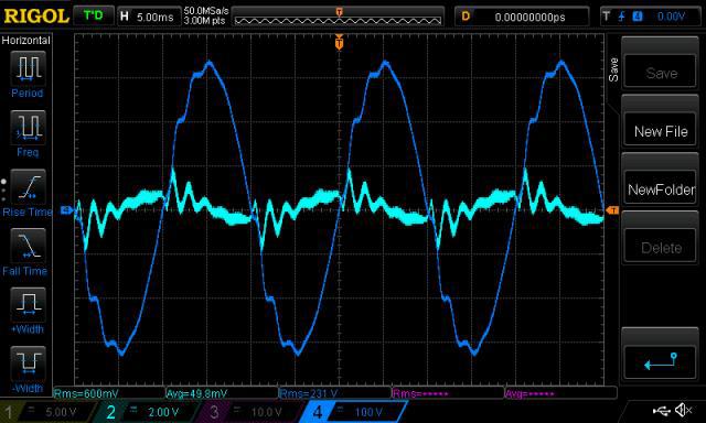 We cannot move this natural resonance higher, but we can easily move it lower. Unfortunately moving it lower can make the problem worse as it may then lock onto an even lower harmonic which will have an even greater amplitude. If we resonate the transformer to 50Hz exactly, that would eliminate the harmonic wobbles and create a beautiful sine wave shape, but that would create an even bigger problem. There could be a massive resonant buildup of energy at 50Hz, the inverter output voltage may become uncontrollable at no load, and rise dangerously high. The solution is to shift the resonance to exactly 1.5 times the inverter frequency. Any stored energy on one cycle becomes exactly out of phase with the following cycle. Its a sort of self damping action that prevents any cumulative buildup of stored energy. This works amazingly well, but in order to work, the transformer needs to be tuned fairly accurately to 75Hz. As your resonance strays closer to either 50Hz or 100 Hz it may start to go a bit wild. 75Hz exactly is the sweet spot if you can manage that. Getting it wrong is not the end of the world, no dire consequences, and its very easy to move the resonant frequency around with a bunch of capacitors. Trial and error adjustment on a running inverter will likely be extremely frustrating and probably will not result in achieving any worthwhile improvement. If you can get your hands on a decent sine wave oscillator and digital frequency counter, it all becomes a ten minute job. Edited 2020-09-07 09:40 by Warpspeed Cheers, Tony. |
||||
| mab1 Senior Member Joined: 10/02/2015 Location: United KingdomPosts: 282 |
Ok, cheers for that. So as long as it's not 50, 100, 150 etc it shouldn't be catastrophic just not pretty. My Chinese inverter board has turned up and I could do with testing it before I start modding. I can tune the final trans properly, but a quick check on the resonance of the test trans can be less critical well plan B was to buy a fairly cheap function generator with sine wave output (I do have a frequency counter); now it's plan A. Although that does beg the question: Are there pitfalls in buying a cheap function generator as opposed to a decent one? And how do you know if it is decent or not? |
||||
| Warpspeed Guru Joined: 09/08/2007 Location: AustraliaPosts: 4406 |
Cheap function generators generally use a potentiometer with a very dubious frequency scale marked around the knob. That will be fine, as long as you hook up a digital frequency counter to know what the true frequency really is. Wind the sine wave amplitude flat out, and connect it to the transformer through a high value resistor, maybe 10K, but try a few different values. Connect your CRO straight across the transformer winding. There will be a definite peak in amplitude at some frequency, usually several hundred Hz or in the very low Khz range. It will not be a very sharp peak, and its difficult to find the actual exact centre frequency. Wind up the amplitude on the CRO, and shift the whole trace down off the screen, so only the very peaks are visible. Rock the frequency slightly and eyeball the peak as best you can. With a bit of practice and some luck, its possible to repeatedly guestimate within about 1Hz where the peak actually is. The amount of extra capacitance required will vary widely. Sometimes as low as 1.5uF, and sometimes over 10uF. Just use whatever capacitors you have to arrive at a suitable value for the test initially. But finally fit a good quality high voltage capacitor once you know the correct value. I did try this test once, with my ancient old analog spectrum analyser, its set here for 20Hz per division, and the vertical amplitude scale is linear (not in db's). As you can see there is a definite peak in amplitude at a tad over 60Hz with a 5uF capacitor. I did not attempt to tune it properly here, just wanted to try the method. 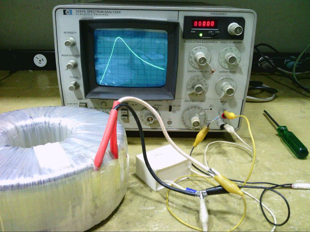 It was not accurate enough to be useful with this spectrum analyser. Much better and more accurate and repeatable results are possible with a manually tuned sine wave oscillator, and an oscilloscope. Edited 2020-09-07 11:37 by Warpspeed Cheers, Tony. |
||||
| mab1 Senior Member Joined: 10/02/2015 Location: United KingdomPosts: 282 |
That's great, thanks! I've bid on a 2nd hand function generator and hopefully will have something soon. My worry was that the chinese board actually comes with a 4.7uF cap already fitted in the feedback cct and didn't want to set it up with a random small transformer for testing only to find out the hard way that the cap pulled it's resonance into dangerous territory. |
||||
| genetrySid Newbie Joined: 05/09/2020 Location: United StatesPosts: 8 |
Hello all, first forum post here, I have a question about transformers  . I do not know all of the technical details regarding transformer functionality and operation--I never had the patience to bore myself to sleep with stuff that wasn't directly tied to any practical real-life use case. But maybe that's why I have the question... . I do not know all of the technical details regarding transformer functionality and operation--I never had the patience to bore myself to sleep with stuff that wasn't directly tied to any practical real-life use case. But maybe that's why I have the question...Regarding the above: I would like to know how to calculate the maximum safe DC input voltage for a specific transformer's primary RMS AC voltage. In the above post, you mention a voltage range of "230v minimum....460v maximum" for DC, being an exact 2:1 ratio. Is this kind of a "general rule across the book for SPWM-driven transformers"? I am aware that multiplying the transformer's primary RMS AC voltage by the square root of 2 (i.e. 1.414) will get the "perfect world" answer for the minimum DC voltage required for a true sine wave. If I use 28vAC (for a 48v system), that's 28 * 1.414 = 39.6vDC absolute minimum. Does this mean that the absolute max DC voltage would be roughly 79vDC? I ask because it's been several times that I've tried to run a Power Jack inverter at a good bit above the originally specced voltage. All 3 attempts have resulted in the magic smoke explosively exiting the FETs. I'm not sure whether this is due to some transformer design rule...the terribly mismatched and imbalanced FET drive...or a combination of the label on the top, the front cover of the inverter's user manual AND last night's barometric pressure in Antarctica??? First one was running a "24v, 5kw" PJ inverter (spec 16v on the tranny primary) at 40vDC (36v nominal). Worked fine at no load, and with resistive loads (1500W space heater), no complaints. Tried plugging in a 1/2hp old-fashioned slow-speed air compressor...and the inverter couldn't start it. (Talk about a first for a low-frequency inverter.) Tried a 2nd time, and a set of deep-fried FETs were soon on the menu for the main course, albeit with a smidge of loss due to splatter out of the deep-fryer... The 2nd and 3rd attempts were running a "48v, 15kw" PJ inverter (36v->230v tranny, I believe...though it could have been the older 30v->260v) on a system that could run up to 68vDC. Same thing...worked fine at no load and with resistive loads, but plugging in an air compressor lit the fuse in the FETs, and the firecrackers went off...though without sufficient propellant for a noteworthy display. If the latter case was a 30v-260v PJ tranny (running 240vAC out), did I hit the "magic smoke" line? I am guessing--could be completely wrong--that this "magic smoke line" has to do with magnetic saturation of the tranny's core. I'm quite aware that if the wire used for the tranny primary, was connected to FETs WITHOUT the core, they would instantly blow up, due to the practical zero resistance. If this is the case, how do I calculate this magnetic saturation point? It seems to have some connection to the load on the transformer--otherwise the inverter would blow up at zero load. But it's possible to run a 16v primary at 55vDC at no load...I've done it. With that in mind, if I spec a 48v inverter (U.S. market, so 240v, 60Hz) for 28v->240v, I have a paper minimum of 40vDC for the desired output AC voltage. Does that mean I have a paper maximum input of 80vDC?? (I'd be more than happy with 70v.) |
||||
| Warpspeed Guru Joined: 09/08/2007 Location: AustraliaPosts: 4406 |
First thing you need to realise is that whatever type of inverter this is (PWM or a Warpverter) all of the voltage regulation is done by controlling the waveforms driving the mosfets. The transformer itself has a FIXED turns ratio, and therefore a fixed voltage ratio, primary to secondary. Its the electronics that adjusts and regulates the turn on and turn off times of the mosfets and hence the inverter output voltage. The electronics can only reduce the voltage going into the primary of the transformer, which it can do quite well. If you have a +48v dc rated inverter, the ratio of the transformer might be about 8:1 so that 30v rms sine wave in the primary generates eight times the voltage in the secondary, or maybe 240v rms. The inverter drives the transformer ALWAYS with 30v sine wave across the primary to generate 240v across the secondary. The dc input voltage could be +60v, or as low as about 43v and it will work fine. The transformer never sees that full 60v, only 30v rms ac across the primary. Now if you put in more than the max rated input voltage rating, the mosfets might only have a 60v rating for example. If you feed in +80v dc or +100v dc its very likely going to go *BANG* and that has nothing to do with the transformer. If a Warpverter is designed to operate with a minimum dc input voltage of say 200 volts dc to generate 235 volts final sine wave, it will work with +200 volt minimum and up to +400v maximum. PROVIDED the switching devices are safe operating at 400v !! I have no personal experience with Power Jacks, but the mosfets they use have a fairly low voltage rating, and Chinese mosfets may also fail through quality control issues. And that is much more likely to happen if you start pushing any of the ratings right up to the limit. Cheers, Tony. |
||||
| genetrySid Newbie Joined: 05/09/2020 Location: United StatesPosts: 8 |
OK, have to say that I know a fair bit about the FET ratings, gate drive, PWM, etc. It's the tranny that's the "great frontier" for me. I am almost 100% positive that if the FETs short the tranny 100% duty cycle across the battery, they will blow due to overcurrent. Had a board manufactured with a fault (still haven't traced out the issue!), where when the MCU tried to start the inverter, it'd short the tranny across the power source. In my case, that was an 8 amp power supply--but the filter caps still had more than enough "oomph" to instantly (and silently) blow the FETs. Kinda funny to see the ferrite choke "jump" with the extreme surge of power...but the FETs were instantly toasted. Blew 2 sets of FETs before I figured out that they weren't the problem. EDIT: NOTE: This was from a production run of PCBs--it was not a design fault, as thus far every other board in that production run has worked perfectly. That seems to be a somewhat important clue to me that there's some factor of transformer design that could specify a maximum DC input voltage rating. I am aware of the "inductor charge" curve, where the resistance returns to zero after the core is saturated--which would blow the FETs. Because the exact same air compressor starts without hesitation when an inverter has a tranny with a more "optimum" voltage specification, no smoke. I dunno. Sounds like you're saying there isn't a theoretical SPWM voltage limit for a specified winding ratio? Yes, I know there's FET ratings, etc., etc., but discounting those... Discounting the choke saturating (i.e. passing the SPWM through into the tranny), wouldn't a low voltage coil go to saturation much easier with very high voltage spikes? I agree that with a perfect SPWM filter circuit, the tranny wouldn't have the slightest care if the DC input was 40v or 4,000v. But real life isn't perfect, and my experience hasn't been the best, so...that's why I asked ;-). Have to say that I have not tried such abusive tests on my personally designed inverter (as opposed to a PJ), so I'm more just asking to see if there's any science behind the madness... Edited 2020-12-29 12:08 by genetrySid |
||||
| genetrySid Newbie Joined: 05/09/2020 Location: United StatesPosts: 8 |
Another thing I've noticed on both hacked PJs and my personally designed inverters, is that as I increase the DC input voltage, the no-load current remains the same (as the inverter throttles the SPWM back to maintain the same output voltage). On a 24v PJ inverter (15->260v), I went from 20v to 45v on a test, and the no-load current did not change. All that extra power is going somewhere. I dunno if this makes any sense...maybe none at all. |
||||
| Warpspeed Guru Joined: 09/08/2007 Location: AustraliaPosts: 4406 |
Transformers do not have a dc voltage rating. If you switch dc across any inductor, choke, or transformer, the current rises linearly up to some point, where magnetic saturation begins, and the current then spikes up limited only by dc resistance of the winding. The rate of current rise is also proportional to voltage. You can switch the dc on and off, and as long as time x voltage remains below some limit magnetic saturation will not occur. If you switch fast enough, amazingly high applied voltages are possible. With any inverter the idling current is mostly from the magnetising current in the transformer. If the primary is fed with a constant regulated sine wave voltage, you would expect the inverter idling current not to vary by much as the dc input voltage is changed. Cheers, Tony. |
||||
| genetrySid Newbie Joined: 05/09/2020 Location: United StatesPosts: 8 |
What you say makes a lot of sense as far as "switching fast enough"--I know the PJs are incapable of switching FETs cleanly...and heavy load on FETs being run in their "linear" region, is a surefire way to cause fireworks. Yes, I'm aware that there is no "DC voltage rating" on an AC transformer...but in the context of a DC-powered SPWM inverter, I'm trying to figure out if there is an inherent DC voltage limit of the whole design (apart from the FET, capacitor and IC ratings). Yes, I understand that the idle current is mostly magnetizing current in the transformer. However, my point is that the DC input wattage goes up with increased DC input voltage. 21vDC * 0.8A = 16.8W...but 29v * 0.8A = 23.2W. Same AC output voltage (regulated within 0.15vAC). If I carry that to 45v * 0.8A, that's 36W...over double the idle current at the start. (This test result is the same on a PJ inverter...as well as one I've designed, which cleanly drives the FETs with a fully matched set of 4.0A drivers. Runs a very quiet transformer when compared to a stock PJ.) Since the magnetizing current on the tranny does not change if the AC input voltage is the same, then what gives?? Where's all that extra power going?? I know, it isn't an Ozinverter I'm working with, so it's probably not making too much sense. |
||||
| nickskethisniks Guru Joined: 17/10/2017 Location: BelgiumPosts: 481 |
I think it makes sense, but this could be caused by a lot of reasons. May I ask which fets you are using for what voltage? It’s wise to use fets that are 1,5-2 times the voltage rating you want to use them for, especially in crappy designs. Crappy designs could be the cause you have oscillations or shoot through events, or are causing spontaneous turn on. It’s wise to probe your gate drive and drain-source of your mosfets, higher currents will cause more trouble. A mosfet gate will behave differently when there is a higher DS difference, maybe not a lot. The soa curve of a mosfet is also very interesting to watch. You say you have a capable gate driver, but sometimes it makes sense to switch at slower speed and have higher switching losses, but this will reduce deadfull oscillations and shoot through events. Is there an inductor between your H-bridge and transformer? If there is, maybe it’s not adequate enough and you need a bigger core that’s saturating at a higher current. Higher voltages will cause faster current ramp ups. Your no load current should lower with higher voltage, try experimenting with that inductor. Leave the 50uH or not, more inductance could slow down the di/dt more (if it's not saturating), but could mess a bit with the sinewave, but use a bigger core (higher saturation point). All that extra power you are loosing under no load? Probably in the core of your transformer, probe your SPWM at your primary (30-36VAC?) with a scoop. You can see when your inductor is saturating on the scoop. You can measure the current going in your transformer with a shunt or fast lem (hall sensor), this should give you some clues as well. Normally the transformer is not fast enough to cope with the fast spwm, that’s why you need an inductor between H-bridge and transformer. If it’s not slowed down enough the spwm will be shorted by the parallel capacitance on your secondary? Please warpspeed correct me if I’m wrong I’m here on slippery ice. Edited 2020-12-30 06:18 by nickskethisniks |
||||
| Page 1 of 2 |
|||||
| The Back Shed's forum code is written, and hosted, in Australia. | © JAQ Software 2026 |
