
|
|
Forum Index : Electronics : It�s BACK _ K220A Regulator
| Author | Message | ||||
Gill Senior Member Joined: 11/11/2006 Location: AustraliaPosts: 669 |
Well I was pleasantly surprised. Looking for the short cut description for making jug element dump loads to reply on another thread, I found the Oatley K220 is back on sale. Well no longer the K220 but now the new K220A. Back by popular demand I expect. All on a different board with different components and all for a cheap $22 for this shunt regulator. Not bad! Hay? 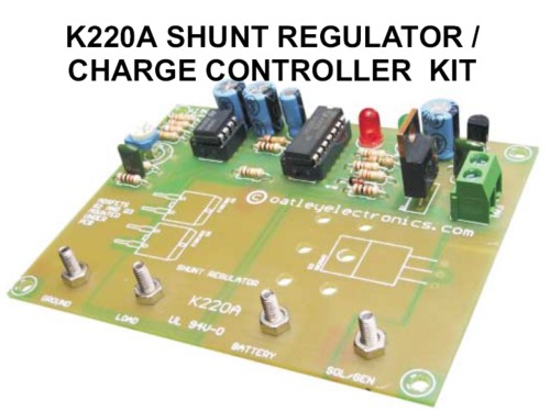
Also a bargain is their 3 phase rectifier using Schottky diodes. Circuit board for mounting with heatsinks and blocking diodes too for $36. 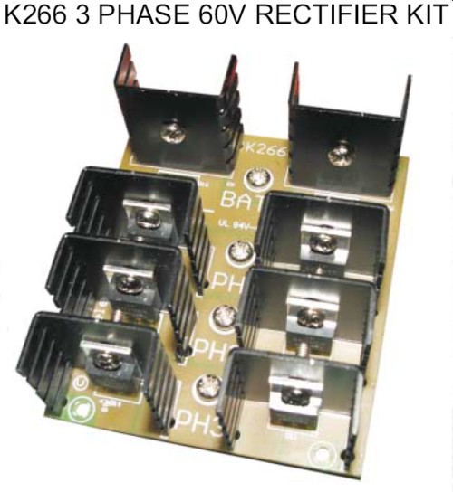
Still haven't received my unsolicited comments payment from last time yet. Will have to contact Lawsy and see how it's done. [joke](Lawsy = notorious Aussie announcer with questionable financial ethics). Gill EDIT: In for a penny....... Here's the LINK to Oatley-K220A was working fine... til the smoke got out. Cheers Gill _Cairns, FNQ |
||||
| Gill Senior Member Joined: 11/11/2006 Location: AustraliaPosts: 669 |
After those reccomendations I find an error. The wind blows at night so the power will feed back through the solar panel with the existing arrangement. I suggest a modification. Origional on Left, Modification on Right 
Ahaaaa! Thats better. Now we have the battery AND the wind gen blocked from feeding through at night. 
was working fine... til the smoke got out. Cheers Gill _Cairns, FNQ |
||||
| GWatPE Senior Member Joined: 01/09/2006 Location: AustraliaPosts: 2127 |
Hi Gill, the photo of the PCB you presented shows 8 heatsinked components. On the schematic, I only count 7 components. Is there an additional blocking diode not shown? Is the battery blocking diode doubled up? Gordon. become more energy aware |
||||
| Gill Senior Member Joined: 11/11/2006 Location: AustraliaPosts: 669 |
G'day Gordon, Yes i think you may be right. The diagram is representative for explanation of layout configuration rather than as schematic. Indeed, perhaps my correction is not of the actual board circuit at all but of a diagram error. Still, good to see a simple readily available shunt regulator for those not wanting or able to build their own. For the first to buy one, Please post a copy of the regulator schematic for online forum assistance and trouble shooting. Thanks. was working fine... til the smoke got out. Cheers Gill _Cairns, FNQ |
||||
| Bluey Newbie Joined: 31/12/2008 Location: AustraliaPosts: 7 |
Hi Gill, Regarding the Oatley K220A Shunt reg/charge controller. I as a newcommer to wind power decided to buy this unit as opposed to building one. This is not a "plug and play" there is a trimmer included which indicates it has to be set up before use, this being the reason for this post. Can you or anyone who is using this regulator help me set it up on the bench before installing it. Blue. |
||||
| Gill Senior Member Joined: 11/11/2006 Location: AustraliaPosts: 669 |
Bluey, I bought many of the earlier K220 but have not seen the K220A so I don't know the circuit. If you have a schematic (circuit diagram) of the unit could you please post a copy for the forum. There is every chance the trim pot is to set the voltage at which it switches from charging to dumping. Different types of battery have different voltages. The battery manufacturers recommendation is your best guide here. A pic of each relevant document that came with the kit would be nice. I think you will need a variable power supply that goes to say 15Volts. Connect it to the battery terminals, and starting at say 12Volts increase the voltage to your chosen set-point. Now adjust the trim pot until it turns on the bump load (though don't actually have one fitted yet). The LED may indicate dumping is in progress? Doesn't the kit instructions tell you how to set this up? As I'm just guessing all this I'd better wait for your pics. was working fine... til the smoke got out. Cheers Gill _Cairns, FNQ |
||||
| Bluey Newbie Joined: 31/12/2008 Location: AustraliaPosts: 7 |
Hi Gill, This kit has a pdf file with it and can be downloaded for appraisal etc but the schematic is not included, this is however included in the copy that comes with the kit once it has been purchaced, I cant post a copy I do not have a scanner, all I have is the printed page. There are no set up instructions as such, but I imagine a more technical person would understand the details that are written in the pdf file and work it out easily. I have a 30 amp power supply but it has a fixed 13.8 volts output, I will experiment with this, that is about the float voltage of most batteries. Blue. |
||||
| Gill Senior Member Joined: 11/11/2006 Location: AustraliaPosts: 669 |
Blue, Enough info is there as you say. If you could post a copy of the schematic to me I'll post it to the forum for reference. My postal address is in my profile. Connections are not clearly defined without the schematic. There are four. There seems to be some options with the supply connections so will leave that 'til last. Battery positive is marked 'Battery' and Battery negative is marked 'Ground'. Simple enough. Now the load (Dump Load) seems to connect from the battery positive 'Battery' to the terminal 'Load'. The Mosfets completing the circuit to ground as needed. As most wind gens are AC, a rectifier is used to make DC. This means no blocking diode is needed and most wind gens will connect direct to 'battery'. If you have a DC wind gen then you will need a blocking diode and this means connection to 'Sol/Gen' for the positive lead. Diode optional extra. Like wise solar panels will need a blocking diode, so two choices here: If solar only then same as DC Wind Gens connection to 'Sol/Gen'. If both solar and AC Wind Gen then the rectifier kit can be used and the blocking diode could be fitted there, so long as it is not at the mast head. Boy this is dragging out...... What I would do is rectify my AC at the masthead, sending the DC to 'Battery and 'Ground'. Then have my Solar connected separately through the optional blocking diode using 'Sol/Gen' and 'Ground'. Why did I start that? I'm sure all are now well confused. was working fine... til the smoke got out. Cheers Gill _Cairns, FNQ |
||||
| The Back Shed's forum code is written, and hosted, in Australia. | © JAQ Software 2026 |
