
|
|
Forum Index : Electronics : AndyMc's OZ/MAD/NANO Inverter Build
| Author | Message | ||||
| andymc70 Regular Member Joined: 30/06/2019 Location: AustraliaPosts: 42 |
Hello All Finally back into the inverter full time now, work, Xmas, and family commitments had put it on hold. Firstly I want to thank Peter for the time we spent together, it was awesome meeting and seeing you and your setup and learning so much from you. Thank you so much. Now onto the inverter, ok I am trying to load the software onto Nano 2. Now I have set up my LCD to use serial and I have run the code above, with changes to the numbers in this line LiquidCrystal lcd(12, 11, 7,8,9,10), to match the blank lines on the Nano 2 in the circuit diagram. Please see the picture below to see what the program is returning on the LCD. 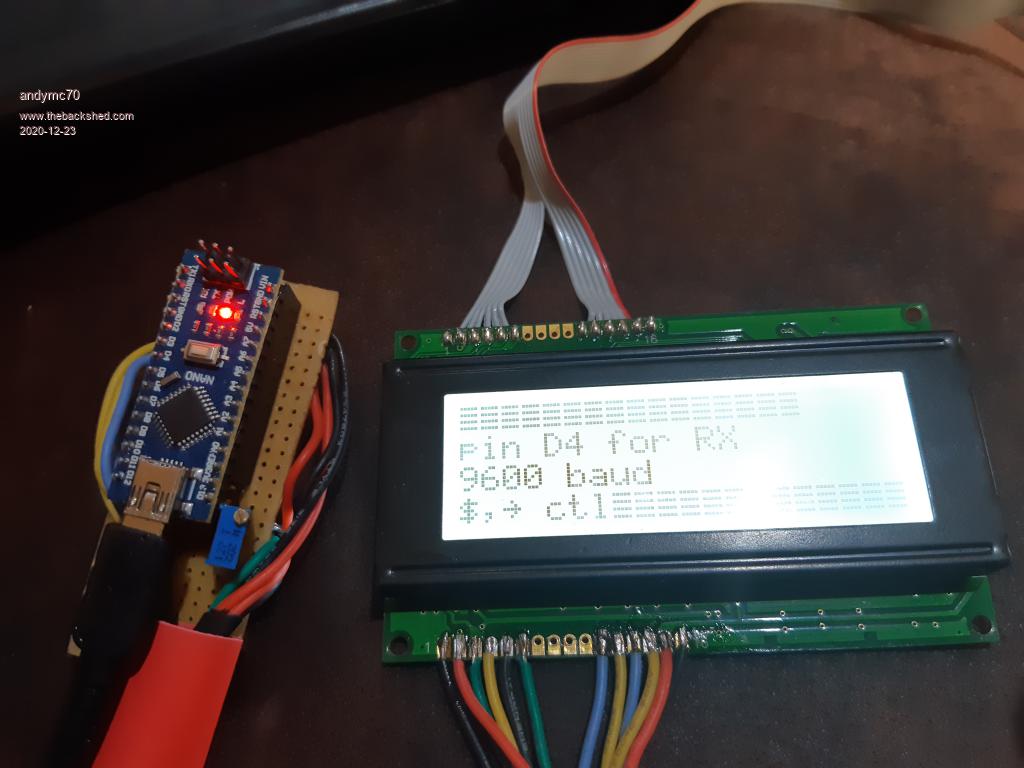 A big tip for beginners a potentiometer is needed to see the screen. I am not sure why the top line looks like it does as when I delete say the bottom 2 prints print("9600 baud"); & print("$,~ ctl"); I then can see the Serial -> LCD printed. So not sure if this is a problem. The other problem I am having is how to put this code and the nano2_5_ac_current_sensor_continuous_on_off_control_softserial together onto the nano 2. If someone can help with this that would be great. I am about to finish the nano control board and add power as I go. The powerboard is ready to go. So I just need to put some cable lugs onto the transformer and choke as well as finishing the switch and Feedback transformer connections and then I am ready for testing. If someone can help me thru the before, during, and after testing procedures that would be great. Thanks Andy |
||||
| poida Guru Joined: 02/02/2017 Location: AustraliaPosts: 1387 |
"The other problem I am having is how to put this code and the nano2_5_ac_current_sensor_continuous_on_off_control_softserial together onto the nano 2." Are you saying you think you need to flash both programs into the one nano? If so, that is not what is needed. The inverter (nanoverter control board) needs two programs, one each for the two nanos that are on the board. And yet another small program for the nano that drives the LCD. But first, well done to get the LCD going. And yes, sometimes you need some sort of voltage between 0 and 5V to make the LCD show a usable contrast. I bought a few LCDs that work fine with 5V on the contrast pin. Others I have needed a pot to tune the voltage "just so" The firmware "nano2_5_ac_current_sensor_continuous_on_off_control_softserial" is loaded into nano2. Then you need to load the (what I call "proper" code) into nano1, which does the real work. something like "nano_1_v7_no_bessel" Using the software serial firmware for nano2 will be best, since it will work if there is a LCD present or not. There is no further work to do with nano1 once you load the firmware into it. Nano1 only does one thing: run the inverter. Calibration is only concerned with nano2. This is where we set the AC output voltage and other parameters. If you want, come on over again with the powerboard and nanoverter control board after New years and we can bring it up safely and calibrate it to some extent. wronger than a phone book full of wrong phone numbers |
||||
| andymc70 Regular Member Joined: 30/06/2019 Location: AustraliaPosts: 42 |
Hello Peter Yeah, you were correct I thought I had to add the code to nano2_5_ac_current_sensor_continuous_on_off_control_softserial but I understand now. I need a 3rd nano to run the LCD is serial, this is no problem, I have a few spare nano's. I have just re-read one of your posts and I think I have it understood now. I am going to use the I2C plug on the nano board but only use 3 wires, TX->Pin3 and 5v and ground. Now the TX wire goes to the 3rd nano pin D4 and the other wires to 5v and ground. I hope this is correct. Peter, defiantly like to take you up on that offer of coming over, unfortunately, it will have to be mid-January as I will be heading back home to Newcastle to see my parents and family. I hope this is ok. Also, I have bought a push-button switch to charge the caps up before start-up, sorry I forget how you wire it. Thanks Andy |
||||
| poida Guru Joined: 02/02/2017 Location: AustraliaPosts: 1387 |
No probs about the timing for the visit. Prove one bit works, prove the next bit works, etc. That's how I like to do it. I use a 10W 33R resistor to charge the caps. We only push the button for a few seconds but that is enough to bring them up to near enough voltage. Then switch over. Jaycar has a 27 Ohm 10W part, that will do fine. 3 nanos to drive the nanoverter seems a bit silly but it works really well and is rock solid. (I read somewhere a note on how many controllers there were built into a modern BMW car. I think the number was one hundred. So it appears to me that dividing the work and roles into smaller, easier to debug, provably reliable parts is the way to go) wronger than a phone book full of wrong phone numbers |
||||
| Warpspeed Guru Joined: 09/08/2007 Location: AustraliaPosts: 4406 |
That seems to be the way things are going. Some little mystery module with a completely unmarked microcontroller chip to make the eight speed windscreen wipers work. After ten years the modules become obsolete and no longer made, and are unobtainable. If your windscreen wipers ever stop, time to scrap the whole car. Cheers, �Tony. |
||||
| InPhase Senior Member Joined: 15/12/2020 Location: United StatesPosts: 178 |
Tell that to the 1978 Mercury Cougar I had. When the wiper switch died, several light switches appeared on the dash for different wiper speeds... Edited 2020-12-24 22:49 by InPhase |
||||
| andymc70 Regular Member Joined: 30/06/2019 Location: AustraliaPosts: 42 |
Hello All Well, i finally put it together and tested it using my own torrid. Thanks to POIDA for helping me get everything working at his place. Unfortunately, it's not working correctly at my place, with my torrid. So during the initial testing, the step-down converter on the nano control board blew a 47uf cap. Scared the sh*t out of me. So I replaced the step-down converter, I will buy some 47uf but higher voltage cap this week, as I am using my spare. No sure if it was the cap or I may have had it set up that the -ve out may have touched the heatsink of the 12v voltage reg next to it. 2nd test I go it going and I can hear it wind up, but it's only a low whine, PETER place I could hear I loud thud. I am unsure why I am not getting 240v out of the transformer, I am only getting less than 1v AC on the primary of the transformer and 6v ac on the secondary. i do not have caps on the power board yet. But we didnt have them either at Peters, so have i stuff up the power board. The dc is 48v. HELP any one. Thanks Andy |
||||
| poida Guru Joined: 02/02/2017 Location: AustraliaPosts: 1387 |
here is nano2 firmware for I2C, in case you want to experiment. note the firmware expects the I2C LCD to have an address of 0x3f This address may differ for your I2C LCD. Edit the firmware to suit. But it might help you get a move on in a direction. nano2_5_ac_current_sensor_continuous_on_off_control.zip This uses the run/stop switch as a continuous switch. You don't just pulse it a bit to start it (and stop it) You need to close the switch continuously to have the inverter run. And open the switch to stop it. This firmware is from an early time and I have added a few things since. I prefer we use the serial LCD but I can help you the best I can to get it running. Edited 2021-01-21 19:57 by poida wronger than a phone book full of wrong phone numbers |
||||
| BenandAmber Guru Joined: 16/02/2019 Location: United StatesPosts: 961 |
i am sure i have not a clue but the dot on tranny? i am so jealous you got to meet poida he is amazing be warned i am good parrot but Dumber than a box of rocks |
||||
| andymc70 Regular Member Joined: 30/06/2019 Location: AustraliaPosts: 42 |
Hello All Thanks to Peter I finally got the Inverter to work on my toroid. I had the battery going throw the heat sink and Peter said that wasnt the best way to do it, so I changed it back to the board and bingo 240VAC out of the inverter. The next problem was the LCD, finally got that working as well. I need to pay more attention when desoldering, when to remove wires from the LCD I found I had short circuit some legs, fixed them and bingo. 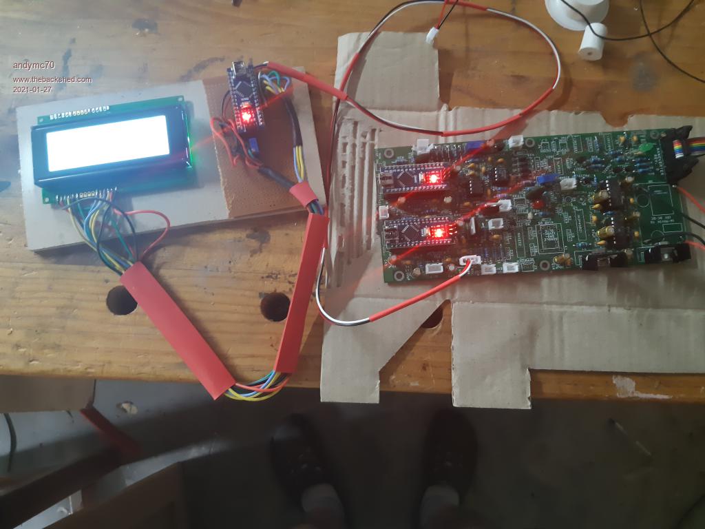 Now I have been making the container, cut the fan holes out, that was fun. Sorting locations for everything. Been designing some fan guides and some spacers for the boards. 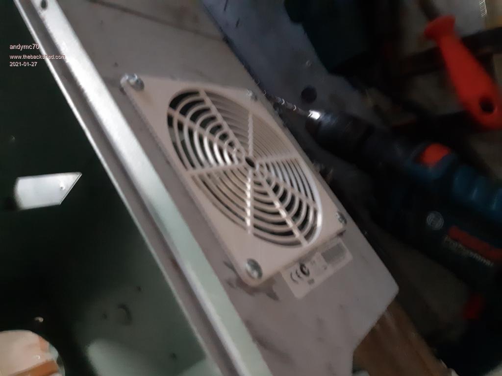 Trying to get the whole inverter running, I just wondering how people have earthed their inverters. Also, I wonder how people have soldered up the large caps on the powerboard, do I just go ahead and solder all cap and place the heatsinks on and put it all together. Thanks Andy |
||||
| poida Guru Joined: 02/02/2017 Location: AustraliaPosts: 1387 |
Andy: good to see it working. I think you are using the fully populated powerboard. Is that true? The next steps would be heatsinks, making sure there is space enough for the large caps. Then fit the caps. I think you have a large soldering iron that can dump a lot of heat so that's sorted. If not, come over to borrow the JCL. When doing the heatsinks, do not overlook that the low side heat sink needs to be cut into 2 parts with a safe and reliable (in the physical position sense) gap. Should they touch when running it will be a short on the transformer primary output terminals. wronger than a phone book full of wrong phone numbers |
||||
| andymc70 Regular Member Joined: 30/06/2019 Location: AustraliaPosts: 42 |
Hello All Finally connected the Inverter up to the shed/home, however not with success. I am having an issue with the RCD in my switchboards. Basically, I have a switchboard in the shed and a MAINS switchboard for the whole house. If I have the Inverter connected only to the shed then it's all good and everything works. However, when I switch the inverter to the mains switchboard it pops all RCD's. My Epever inverter doesn't pop any RCD's I also checked earth and they are all connected. I am also wondering, I have connected earth and neutral together in the inverter before the outlet, am I meant to do that? Does anyone have any idea? Thanks Andy Edited 2021-06-17 20:47 by andymc70 |
||||
| wiseguy Guru Joined: 21/06/2018 Location: AustraliaPosts: 991 |
I am having a bit of trouble picturing what your actual physical wiring looks like. The image I have is that you are connecting the inverter to the shed wiring and then throwing a breaker to feed it back the house. With RCD's the current in the active needs to equal the current in the neutral. As you have connected neutral to ground at the inverter in the shed, is it possible that some neutral current is passing through the house & shed grounds and therefore unbalancing the neutral/active current in the RCD?. I would disconnect the earth at the inverter and try it gain - the neutral does/should? become grounded at the switchboards neutral/ground connection anyway? If you could sketch a bit of a mud map of how it is wired would perhaps help identify the issue/remedy ? Does the Epever inverter have the neutral and grounds tied at the inverter - I'm guessing not ? If at first you dont succeed, I suggest you avoid sky diving.... Cheers Mike |
||||
| InPhase Senior Member Joined: 15/12/2020 Location: United StatesPosts: 178 |
Connecting the earth to neutral in the inverter is what is causing the tripping. There is a loop for some current to bypass the RCD, which it senses as a fault and opens the circuit. |
||||
Madness Guru Joined: 08/10/2011 Location: AustraliaPosts: 2498 |
Neutral and earth are only bonded at the switch board as per the previous post. Also there must only ever be one earth stake, multiple earth stakes would have a very large potential difference if you had a close lightning strike. There are only 10 types of people in the world: those who understand binary, and those who don't. |
||||
| andymc70 Regular Member Joined: 30/06/2019 Location: AustraliaPosts: 42 |
Hello Thanks for all the advice, removed the E-N connection, and it's working now. Did a load test and it worked until the DC voltage tripped at the correct low voltage. I am assuming it meant to make a humming noise when working. Now just waiting for some sun in sunny Melbourne. Thanks a lot Andy |
||||
