| Author |
Message |
domwild
Guru

Joined: 16/12/2005
Location: AustraliaPosts: 873 |
| Posted: 11:22am 12 Sep 2008 |
 Copy link to clipboard Copy link to clipboard |
 Print this post |
|
Hi,
Managed to scrounge three power supplies. Picture is on Fieldlines under "Controls". As I asked one question there I do not wish to ask more questions.
This power supply gives me 5 VDC and 12 VDC, which is great to drive a PIC on 5V and FETs via 12V.
Problem: A 10 VAC supply is used, which is 10 x 1.414 or 10 x root 2 peak voltage going into the diode followed by a 5V and a 12V regulator. It gives me 5.00 VDC OK but 12.8 VDC on the other pins.
The SI-3122P regulator regulates from 15 VDC up to 35 VDC, at the low end it becomes 11.8 and at the high end 12.2 (as per datasheet).
But the output is 12.8 V. Is the 14.1 V AC peak input confusing the regulator as the min. input should be 15 as per speci??? Do I have to go higher with my AC input??
THANKS.
Taxation as a means of achieving prosperity is like a man standing inside a bucket trying to lift himself up.
Winston Churchill |
| |
CraziestOzzy

Senior Member

Joined: 11/07/2008
Location: AustraliaPosts: 135 |
| Posted: 11:48am 12 Sep 2008 |
Copy link to clipboard |
Print this post |
|
Is it my understanding that your external power supply to your unit is a 10 volt AC supply, assuming you have a transformer that breaks the (for example) mains supply of 110v to 10? You mention capability of varying the input, so I guess you have a variac, transformer type arrangement to do this?
I cannot see the diagram you referred to is all.
Is the control unit under question, itself a switch mode power unit or transformer type?
The SI-3122P I believe is used to stabilize voltage output from a switching unit before final output...both instances rely on DC voltage. So I am at a loss as to how
14.1 V AC peak input -is- confusing the regulator...I am just questioning to clarify what is going on.
The diode you mention that accepts incoming voltage and outputs to the regulators...is it an AC/DC rectifier?
Guess a schematic or something like a picture would help a dumbass like me  Edited by CraziestOzzy 2008-09-13 Edited by CraziestOzzy 2008-09-13
http://cr4.globalspec.com/member?u=25757
http://www.instructables.com/member/OzzyRoo/ |
| |
domwild
Guru
Joined: 16/12/2005
Location: AustraliaPosts: 873 |
| Posted: 05:44am 13 Sep 2008 |
Copy link to clipboard |
Print this post |
|
Crazy,
Thanks for that. No wishing to load Gizmo's disks full, why don't you look at Fieldlines, section Controls. A full explanation is there and a photo.
But to save you the work:
My AC input, which was unknown until it was answered by wpwokalup is 10VAC; have to check that. This input goes into two separate diodes, then into various caps, then into two regulators. This seems to be a very primitive supply as it seems to depend on the regulators to get the DC down to 5V and 12V. There is no toroid.
I have not measured the AC input of 10VAC, I have simply gone by the plate on the transformer.
I will also check the other two identical power supplies to check if they behave the same way.
Thanks.
Taxation as a means of achieving prosperity is like a man standing inside a bucket trying to lift himself up.
Winston Churchill |
| |
oztules

Guru
Joined: 26/07/2007
Location: AustraliaPosts: 1686 |
| Posted: 05:55am 13 Sep 2008 |
Copy link to clipboard |
Print this post |
|
Here Crazy:
Village idiot...or... just another hack out of his depth |
| |
CraziestOzzy
Senior Member
Joined: 11/07/2008
Location: AustraliaPosts: 135 |
| Posted: 09:42am 13 Sep 2008 |
Copy link to clipboard |
Print this post |
|
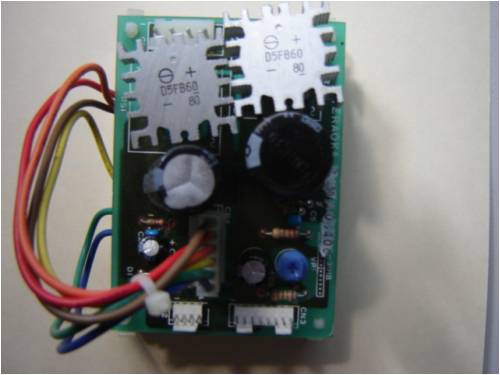
Ok...here is what I see here...two separate bridge rectifiers with a capacitor for each diode....one capacitor valued higher than the other...which means you have two separate input voltages. The inputs are sitting at the top of the photo where the pin slots are. I would bet a brass monkey the solder trace on the back actually shows the two rectifiers hidden underneath the heat sink at top of photo are actually isolated in the initial circuit. Overkill but works all the same. If that is the case you need two separate voltage inputs of AC.
I would guess the variable resister coloured blue bottom right is to fine tune voltage output, possibly fine tune the higher voltage output from the larger capacitor?
All components south of the two large capacitors are DC and not AC.
I take it you are measuring the voltage outputs from the terminal of wires you have hidden behind the board?
ANd a final question for yuh, where are the SI-3122P's?
PLease shoot me if I am wrong...am just surmising that those rectifiers up top are not just two shottkys joined together to make four and thus a bridge rectifier.Edited by CraziestOzzy 2008-09-14
http://cr4.globalspec.com/member?u=25757
http://www.instructables.com/member/OzzyRoo/ |
| |
GWatPE
Senior Member
Joined: 01/09/2006
Location: AustraliaPosts: 2127 |
| Posted: 10:12am 13 Sep 2008 |
Copy link to clipboard |
Print this post |
|
I think the question was, Does the input AC [10V] need to rise? A different plugpac, say 12VAC might do.
Gordon.
become more energy aware |
| |
CraziestOzzy
Senior Member
Joined: 11/07/2008
Location: AustraliaPosts: 135 |
| Posted: 02:58am 14 Sep 2008 |
Copy link to clipboard |
Print this post |
|
well, I might be wrong...I see no torroid in conjunction with a FET switch nor do I see any DC voltage regulator here, except a few low amp resistors that may be prone to overheating if you use higher AC input voltages to control your DC output voltages.
This photo in my view shows just a PCB board that has been doubled up to save room to rail two distinct voltages from one end to the other with the primary purpose of converting AC to DC.Edited by CraziestOzzy 2008-09-15
http://cr4.globalspec.com/member?u=25757
http://www.instructables.com/member/OzzyRoo/ |
| |
domwild
Guru
Joined: 16/12/2005
Location: AustraliaPosts: 873 |
| Posted: 03:28am 14 Sep 2008 |
Copy link to clipboard |
Print this post |
|
Thanks for help.
Yes, the two regulators are underneath the main board and are fed via the cables seen on top.
Yes, you have guessed correctly. Now that i am having problems with the higher output voltage I looked at the board more closely and noticed the "VR" marking or variable resistor with a blue top. Have not played with it yet but it must be there then, as you have suggested, to bring down the higher output voltage.
Also noticed, the AC transformer says 10 VAC on the plate but is actually a 12VAC output.
To say "Shottky" was my error; there are two separate rectifiers splitting the input AC onto two wide solder tracks and then to the two full-bridge rectifiers.
At the bottom end of the photo are two sets of pins. One lot gives me the 5VDC, the other the 12.8VDC.
There must be a good reason why the variable resistor is there despite the fact that the data sheet for that 3122 regulator claims to output 12.2 even when fed with 35VDC.
Not to worry, you have fixed my problem by leading me towards the VR for the high-voltage DC ouput.
Thanks.
Taxation as a means of achieving prosperity is like a man standing inside a bucket trying to lift himself up.
Winston Churchill |
| |
