
|
|
Forum Index : Electronics : Computer PSU Conversion
| Author | Message | ||||
Bryan1 Guru Joined: 22/02/2006 Location: AustraliaPosts: 1209 |
Hiya Guys, Well thanks to Oztules and Dinges I've decided to embark on a major headache(PSU conversion). I'm using the old psu out the my computer that died and it's plain to see why it bit the dust. What looks like a 2-3 watt sense resistor sort of got hot and melted the outer casing off the resistor. On measuring it with my dmm it measured 6.8 ohms so hopefully thats correct. Here's a pic of the psu box 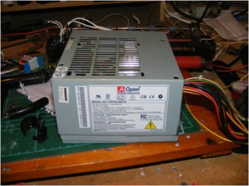
A pic of the toasted resistor 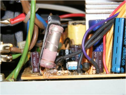
Top veiw of the psu 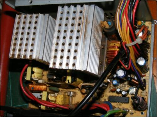
Side veiw of the psu 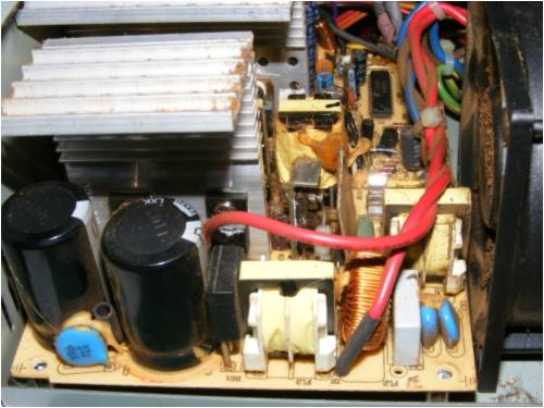
The main chip is a KA3511 and I mananged to find the datasheet for it. I searched the net for hours trying to find a schematic with no luck so now the fun will start tracing where everything goes and making one. Cheers Bryan  |
||||
| GWatPE Senior Member Joined: 01/09/2006 Location: AustraliaPosts: 2127 |
Hi bryan, probably a short somewhere, to cook that resistor. Gordon. become more energy aware |
||||
| Dinges Senior Member Joined: 04/01/2008 Location: AlbaniaPosts: 510 |
Bryan, Don't you have a PC PSU that's working and uses a TL494 ? That would make the modifications much easier when doing it for the first time. This PC would have to be repaired first, and then you'd still have to modify it. I haven't seen any PC PSU which didn't use the TL494 or an equivalent; the KA3511 is quite different. You'd also have to trick the over/undervoltage protection (on pin 13/14/15/16); ALL these pins must satisfy the KA3511 (3.3, 5 and 12V) for it to work, if I'm understanding the working correctly; you probably would have to rig up something with a few zeners being driven off a 14-15V spare voltage (IC powersupply ?) to keep that part of the IC happy. Pin 4 is the voltage error amplifier, the part where you can add a potmeter for voltage control. Unfortunately there's no 2nd opamp that could be used for current control purposes; another advantage of the TL494/KA7500. Without knowing the exact schematic, I suspect that resistor loads one of the voltage outputs to provide a load to keep the PSU happy. If it's loading the +3.3V output it would draw about 0.5 A, which seems reasonable. Also, 6.8 ohm is a standard value for resistors, so me thinks the resistor is fine, even though it shedded its skin. Hard to see in your pictures, but does the transformer have a centertap (ground) with flying lead ? That would be handy for current control. On current control... I don't see a 2nd spare opamp in the KA3511 you could use, as you can in a TL494 (=KA7500). It's not a PSU I would like to tackle for a first project, but maybe you enjoy the challenge... 
|
||||
oztules Guru Joined: 26/07/2007 Location: AustraliaPosts: 1686 |
Bryan, Dinges has said it all really. The pins 13-16 can use a voltage divider network to provide the necessary fool it voltages, perhaps with a zener (15v) across the pin 1 to ground to provide stable reference for these pins (run the divider from pin1) You can use the onboard opamp for voltage, but will require another off chip opamp to drive pin2 with the current information. There will be a center-tap there for the halfbridge operation, but is not absolutely necessary, as any flylead will give you the biasing you need to drag an op-amp below ground for current info purposes. I agree with Dinges, that the resistor is purely a load resistor, and is probably down but not out. It would have failed high resistance if it were dead. If you can pull this one off, I will be happy to give you superstar psu status, as it will be unusually messy, and best not attempted as a first try, as there will be thousands of better candidates available to you. This one has the secondary little flyback power supply in there as well, which only serves to complicate the first try conversion. Try and rustle up an old xt power supply, it will be much more rewarding. It's not that it can't be done, just not worth doing when there are other easy ones available. .........oztules Village idiot...or... just another hack out of his depth |
||||
| Dinges Senior Member Joined: 04/01/2008 Location: AlbaniaPosts: 510 |
Bryan, your story caused me to google and read a bit more on this topic. Stumbled upon this website that has a few schematics as well: http://www.smps.us/computer-power-supply.html And here's another typical schematic of a PC PSU using the TL494 & LM339: http://www.users.on.net/~endsodds/230cct.jpg Odds are high that a normal PC PSU (using the TL494) you get your hands on is nearly identical to one as in the schematics above. Oztules, on this site (http://www.users.on.net/~endsodds/smps.htm) they actually rewind the transformer too to convert it to a 13.8V/20A powersupply. Transformer rewinding info here: http://www.users.on.net/~endsodds/tx.htm) Interesting, looks to be an Aussie website too. I may have to give this modification a go myself sometime... If only to power the shortwave radio that's still on my 'wanted' list. (ok, so, I have no real use for it now... But I still want one!) |
||||
| Bryan1 Guru Joined: 22/02/2006 Location: AustraliaPosts: 1209 |
Hiya Guy's, Well thanks guy's on the info above and when I read the datasheet for the KA3511 I thought I was in for a good headache. The local market does have some old P100's so I'll go se if if I can wrangle one for free or the prinecly sum of a gold coin donation. All is not lost with this psu as with a bit of fiddling it could serve as a power supply for my cnc project. This morning i'll short pins 14 and 15 on the 20 pin connector and see if this psu is still working and if it aint I'll have some real nice heatsinks for other projects. Cheers Bryan  |
||||
| oztules Guru Joined: 26/07/2007 Location: AustraliaPosts: 1686 |
Dinges, Good link. I remain less than excited with the layers of the rewind, too much unnecessary leakage with seperate primary/secondary topology. I think the original manufacturers were right in winding the primary both inside and outside the secondary to get good flux linkage. I also prefer to cook the transformer in a pot of boiling water to allow pulling it apart... not keen on the stripper stuff at all. Interesting that he has no current regulation, only over current.... not much good for my experiments, where low current limiting is the only thing between me and total destruction of sensitive circuits, but a very informative read just the same. In the guise he has it, it will not drive a low impedance load... it will undervoltage and over current... for a few more components, he could have a useful device, rather than just another iffy supply, that will only power selected devices... for all the work he has put into it, it is barely better than the unmodified unit with voltage control set to 13.8v. 
If you rewind the tranny.. don't, get a larger core and go from there.... make it worthwhile and go for 400watts or better, or parallel two smaller ones, or physically bond two cores together and rewind them ("E" cores)...Upgrade the filters and make the effort more worthwhile.
POWER!!!! I say... more Power... (insert evil grin here) ........oztules Village idiot...or... just another hack out of his depth |
||||
| oztules Guru Joined: 26/07/2007 Location: AustraliaPosts: 1686 |
Bryan, a reworked xt will be a better low impedance driver than that unit for your cnc. Without current limit, you run the risk of shutdown just when you don't need it...like when the servo's surge on fire up.
Although it would probably perform very well, I don't like the idea of a supply having the last say on whether I am pushing it too hard or not. It's my god given right to drive the motors to destruction I say. 
.........oztules Village idiot...or... just another hack out of his depth |
||||
