
|
|
Forum Index : Electronics : Anemometer electronics ?
| Author | Message | ||||
Bernie the Bolt Regular Member Joined: 26/10/2006 Location: United KingdomPosts: 45 |
Hi guys ! Am trying to get data from a rebuilt professonal anemometer I found in a skip. It only had one cup when I found it so I have replaced all three with measure cups from "Vanish" wash powder and some alu tube(see attached pics) My electronics experience is limited - but I have a multimeter whch will measure Hz and also output via a RS232 to a pc. I was intending to record this data on an old toshiba laptop. BUT ! when spinning the spindle by hand I can record some mv changes but no HZ data. I think reading the meter specs the problem is it will not record less than 10 hz/sec and needs >200mv and I get a lot less than that. At present I am not interested in the wind direction but have indentified which pair of the six wires does what. I have a digital bicycle computer I could use but I was intending to use that to record rpm on the mill. Any suggestions ? Bernie the Bolt I'd rather be sailing! |
||||
Gill Senior Member Joined: 11/11/2006 Location: AustraliaPosts: 669 |
G'day Bernie, From your post I see you are receiving mV changes but no Hz data. This indicates you are metering the existing circuit. It is near impossible to recommend a coarse of action without knowing the manner the signal is created by. Is it by hall effect, reed switch, photo electric etc. For example, how many wires connect to the head, two, three or more? Are you able to pop the top off and take a quality picture of the circuit? There is not much I can recommend without further info. See what you can do? was working fine... til the smoke got out. Cheers Gill _Cairns, FNQ |
||||
| Bernie the Bolt Regular Member Joined: 26/10/2006 Location: United KingdomPosts: 45 |
Hi Gill, Here are pics, the green wire and the black wire going through the hole come from the windspeed sensor. The other wires are from the direction sensor which I am not concerned with. 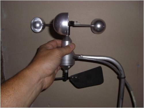
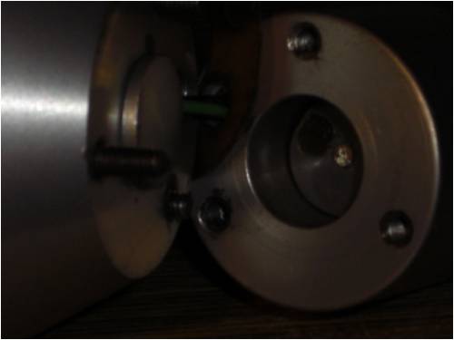
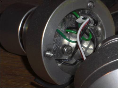
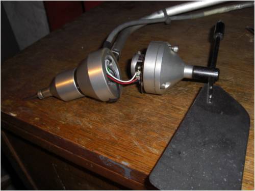
I am guessing there is a small magnet and a coil inducing a small pulsed output ? Bernie the Bolt I'd rather be sailing! |
||||
| Gill Senior Member Joined: 11/11/2006 Location: AustraliaPosts: 669 |
Bernie, Pictures of two wires is no better than saying there is two wires, still without a pic of the device, that is a start. It tends to eliminate some photo electric and hall effect devices. Your idea of magnet and coil is less likely though still possible. What do you get if you put an ohm meter to those wires and turn the cups? This might indicate a reed switch if it pulses on and off. Is there any indication of cogging? If your idea is right I think an amplifier like Glenn uses in the piclog project will be needed. was working fine... til the smoke got out. Cheers Gill _Cairns, FNQ |
||||
| Bernie the Bolt Regular Member Joined: 26/10/2006 Location: United KingdomPosts: 45 |
Thanks for you input Gill. Sorry no picture of actual device, but I cannot see how to strip it down any further. When I rebuilt the cups I balanced them in situ and there is no sign of cogging. However when I tested with a multimeter I did not think of measuring resistance - so I have just done that, and hey presto ! - open circuit for 2/3 of a turn and just over 100 ohms for the other 1/3 rd. So it is a reed switch ? Now I need to build a circuit to measure the pulses and send the output via rs232 to a data logger program on my laptop. Bernie the Bolt I'd rather be sailing! |
||||
| Gill Senior Member Joined: 11/11/2006 Location: AustraliaPosts: 669 |
Bernie, Yes that sounds something like what I would have expected. 100 ohms is higher than I would have thought. So it looks like you will get one pulse per rev. Not good if you have long cup arms. Still, we do not need to measure the very slow wind speeds any rate, just below cut-in and above. Here is a site you may find helpful. Perfect really It suits an anemometers signal just like yours, is simple to connect, and uses no IC's just one resistor. I've tried it myself (sort of)and it looks good. You will need to calibrate it using another anemometer or use the old car method. I don't see a logging function in the software so that's a bummer. Maybe you'll need a picaxe after all. Will give you a readout that can be calibrated to kph or m/s but no logging. This software is good for prop/gen rpm too. was working fine... til the smoke got out. Cheers Gill _Cairns, FNQ |
||||
| Tinker Guru Joined: 07/11/2007 Location: AustraliaPosts: 1904 |
May I suggest you stay away from using reed switches for such a project. I found they don't have a long enough service life - used 16 of them to indicate wind direction and they started playing up after just a few months up on the roof. I now use a 360 degree conductive plastic servo pot voltage divider for the direction (lasts about 10 years) and a slotted disk & opto sensor for the speed (still the original, >20 years). Tinker Klaus |
||||
| The Back Shed's forum code is written, and hosted, in Australia. | © JAQ Software 2026 |
