| Author |
Message |
domwild
Guru

Joined: 16/12/2005
Location: AustraliaPosts: 873 |
| Posted: 09:25am 30 Sep 2008 |
 Copy link to clipboard Copy link to clipboard |
 Print this post |
|
And whoever else is interested, either as an intellectual exercise or actually building it:
Gordon: I realise your work on MPPT has commercial applications and judging by your many graphs, calculations, etc. we can see you have the MPPT problem "licked" so I will not press you on details but offer you congratulations, e.g., the Amps track very nicely the gusts as per the graph on page 4 and the efficiency of your conversion is good.
From what I remember of the five page MPPT discussion, the following has emerged of your construction:
Buck/boost DC-DC converter
Picaxe-based, PWM, frequency and pulse-width modulated
As, no doubt, we are all intrigued how you managed to solve the MPPT problem and only in general outline, can you tell us the following:
1. Is this a SEPIC buck/boost converter or which one?
2. In general pseudocode only, when do you change the frequency and pulse width (up/down) and for which parameter?
I hope this is not a tall order.
Taxation as a means of achieving prosperity is like a man standing inside a bucket trying to lift himself up.
Winston Churchill |
| |
GWatPE
Senior Member

Joined: 01/09/2006
Location: AustraliaPosts: 2127 |
| Posted: 02:24am 05 Oct 2008 |
Copy link to clipboard |
Print this post |
|
Hi Dom,
I must have missed this thread, I have just stumbled upon it. From your enquiry, is this a royal we, or have you had private discussions with others.
WRT your questions.
It is not a sepic converter. It is a highly non linear boost maximiser. I have outlined the issues I see with buck designs, and the problems associated with the necessity to process all the power at the highest levels with a narrower pulsewidth.
With my arrangement, the pulsewidth is determined during each process loop. This value is held constant until updated in the next loop. The pulse width and modulation frequency is updated at the same time.
I have a system where I can model a maximiser and then test it on the mill. I look at the responsiveness and the power over a range of windspeeds. I compare this with my reference windmill. I can perform many mods to the code in a short time.
What I have found is that there cannot be any feedback type response to find a maximum. None of my ccts employ any feedback type calculations. I call it direct control, others have labelled it feedforward, however my process dynamics and control knowledge has feedforward control as something else.
I have said before that I use one feature of the picaxe to frequency modulate, and another to pulsewidth modulate.
The lastest version of my picaxe code, starts loading my F&P windmill at 100rpm to give approx 3-5W output. This is a windmill output voltage of approx 12V. I have found that there is approx 10W that cannot appear in the load at this level, as it is consumed within the alternator. At mill battery cutin output, the power output needs to be approx 70W. Above the cutin voltage, the boost cct function decreases rapidly. The boost cct is effictively bypassed at a mill output voltage about 1V above the battery voltage. I do hope to tabulate a comparison set of data from my test rig, that compares a typical battery only system with a battery+capacitors with battery+capacitors+boost cct. These will all be related to an input power level and rpm, so overall system efficiency can be compared for each setup.
I suspect that the same procedure I have used may be required to tailor a maximiser to a different setup. This will require spreadsheet manipulation, graphing skills and picaxe reprogramming, realtime recording and graphical display of at least mill voltage and battery voltage and current, display of calculated power. windspeed would be useful as well, but if the task is done at the windmill, then mill responsiveness when compared to power output is a good indication of performance.
At the higher power levels, the windmill tracks the power pretty well, up to a point where furling takes over.
I believe the windmill has to be disigned to at least achieve battery charging voltage at around half the expected maximum mill rpm, without caps, or maximiser.
For a F&P alternator, a boost cct takes care of the bottom end of the power levels and caps look after the top end.
I had expected to see some sort of commercial windmill Maximiser/MPPT on the market by now. This debate has been discussed on several forums for years now. It is quite clear that a windmill cannot achieve maximising without some electrickery help. I see the maximising function of benefit at the lower power levels, to give output power where normally it would not be available. Design a windmill to match the load well, without help at the top end power levels only. Windmills can produce relentless power in certain conditions and reliability dictates a kiss principle at these times.
Gordon.
become more energy aware |
| |
domwild
Guru
Joined: 16/12/2005
Location: AustraliaPosts: 873 |
| Posted: 07:59am 07 Oct 2008 |
Copy link to clipboard |
Print this post |
|
Gordon,
Thanks for that.
It was a royal "WE" as I am sure i am not the only one whom you kept in suspenders in how you engineered the Maximiser problem.
I will have to read your comments many times over to comprehend them.
Didn't I see an Air-X ad claiming to use MPPT for their mills and the comment on Fieldlines that one member tried to reverse engineer their electronics?
You may or may not have seen my comments, probably on Fieldlines.com re brazilian Masters thesis on SEPIC converter, MPPT and power factor correction. As it is at your level of comprehension (and not mine) I can dig up the link, if you are interested. Not the whole thesis but a shorter article.
*
Taxation as a means of achieving prosperity is like a man standing inside a bucket trying to lift himself up.
Winston Churchill |
| |
GWatPE
Senior Member
Joined: 01/09/2006
Location: AustraliaPosts: 2127 |
| Posted: 07:24am 11 Oct 2008 |
Copy link to clipboard |
Print this post |
|
Hi Dom,
the sepic converter was discussed on this forum. I made some comments, as did oztules. I saw some holes in the step response time, and issues related to this in the real world.
I present some voltage output responses from my F&P mill with boost maximiser, firstly for a 5min window below cutin.
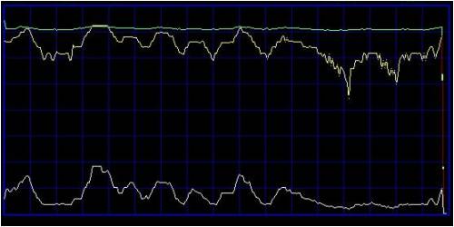
In all graphs, the green trace is the battery voltage. This is a nom 24V battery and the voltage ranged from approx 27.6-28V. The yellow trace is the windmill voltage on the rectifier caps. The white trace is battery current. The voltage is 0-30V full scale. The current has a slight zero offset and is approx 0-18A.
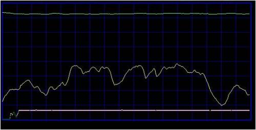
The mill output voltage just rises and falls with the changing rpm. This is 0W output to 24V nom battery.
Next is a 1min window just on cutin.
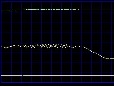
The slight oscillations are at the 0-1W output power to 24V nom battery. The voltage falls off as the mill slows down. This would be about 60-80rpm rotor speed.
This is a trace at a slightly higher power level, 2-10W to the battery, at 100 data sample readings per second.
There is some ripple on the filter caps at this low power level. The current to the battery is more representative of the actual power transferred. There is no rapid change to mill rpm, that would be indicated by the voltage. The maximiser draws the voltage down and then backs off a bit. A lot of the ripple is from the RAW AC coming from the mill that is not completely filtered by the rectifier caps.
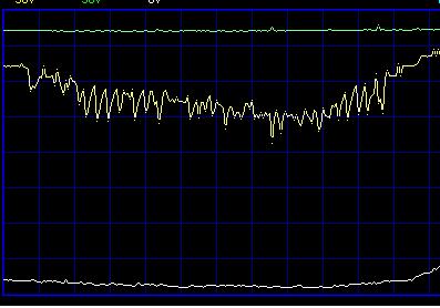
This next graph is between cutin and up to battery voltage.
The windmill voltage is clamped by the battery, at 0.6V above the battery voltage. Current still increases as expected though. The power to the battery is approx 80W when the windmill just reaches the battery voltage.
This next trace is a portion of the above, at 50 data sample readings per second.
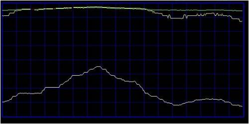
The cct responds very well to the changing windmill energy.
The ripple decreases as the power levels increase, until, above 130W the boost turns off and the bulk of the windmill current bypasses through the main rectifier.
I doubt I can improve much on the performance of this cct.
I do not have suitable recorded data for the top end power levels, where caps would be playing a bigger role. All of these recordings were taken with series caps, so the windmill was capacitor coupled to the load.
Gordon.
become more energy aware |
| |
domwild
Guru
Joined: 16/12/2005
Location: AustraliaPosts: 873 |
| Posted: 02:42am 12 Oct 2008 |
Copy link to clipboard |
Print this post |
|
Gordon,
Thanks for that. Despite being more of a software person I can see the tracking, the ripple and the battery clamping the voltage from your graphs.
Amazing to see the boost starting at the low end and adding a mere watt into the batts.
Congratulations!
Taxation as a means of achieving prosperity is like a man standing inside a bucket trying to lift himself up.
Winston Churchill |
| |
GWatPE
Senior Member
Joined: 01/09/2006
Location: AustraliaPosts: 2127 |
| Posted: 07:13am 12 Oct 2008 |
Copy link to clipboard |
Print this post |
|
Hi dom,
Every mA counts. Efficiency is the hard nut to crack.
My mill today is maxing out the gridfeed cct, so unfortunately efficiency goes out the window. I have said before that I have designed my system for the 80/20 rule. 80% of the time I get 20% of the wind energy.
When I see the systems shut down in really windy weather I sometimes think I need a bigger gridfeed system, but then this has to be weighed up with the times there is not much wind. No point in over capitalizing.
Gordon.
PS edit:
A problem I see with a calculating MPPT is that the loading program will have problems taking measurements without significant filtering. The low frequency ouput
of a windmill at low power levels requires large DC smoothing capacitors, or RC measurement time constants. These create delays that significantly affect control response. Edited by GWatPE 2008-10-13
become more energy aware |
| |
