
|
|
Forum Index : Electronics : Electronic load with energy recuperation
| Author | Message | ||||
| nickskethisniks Guru Joined: 17/10/2017 Location: BelgiumPosts: 409 |
Like always I have the need to start a new project before finishing other projects  . . So this is something I spent my time on the last month, here I go, I was in need to make something to test my batteries on capacity to match the series strings. But since I don�t want to waste that energy I want to put it back in the �main� 48V battery. I liked the idea to use a buck regulator to regulate the current drawn out of the battery. Downside, the voltage only goes down, I could use a boost converter circuit, that would be the most efficient way, but I like galvanic isolation between my main battery and the to test battery. I could have used some kind of switch mode power supply circuit, but I did not have good experience with it. I tried it 5y ago but I wasn�t that �smart� as I�m now. I couldn�t get the transformer and inductor right for current regulation. I know I could probably put something together now but I have more expierence with the buck regulator. � So I went for 2 stages, the buck part were I regulate the current (constant current), and a second stage for the galvanic isolation. A third board will be needed, for controlling the whole thing, I want to use a single Arduino nano for that. That way I could build it bit by bit. The cool thing is, I can use the �concept� to test DC/DC converters with energy recuperation! So basically I can test big DC/DC converters without the need of a big power supply, it�s possible to test for example the 150V 45A MPPT controller without the need of an 3kW+ power supply! A supply is only needed to compensate the losses in the circuit. Or only use the buck circuit and dump the energy in a resistor, or battery with lower voltage. So I have created 2 prototype boards: First board, the buck converter, it has a pre charge circuit with a resistor and mosfet, so no sparks when connecting the battery for the first time. Then there is a mosfet to take over when capacitors in the circuit are charged. There are voltage dividers to measure the voltage on each stage. Then there is the buck mosfet and freewheeling diode, and off course the inductor, the higher the value the smaller the current ripple on the input/output. It uses ACS712 sensors to measure the current. I made a mistake so they are backwards and need an opamp circuit to use them for current regulation with a TL494 pwm IC. This will be fixed in a next version. I will probably add an extra current measurement on the output, because this should be limited as well. But this could also be done in the software. The inductor and diode need to be protected when the circuit is operated out of its comfort zone. The circuit can take 20A on the input and output, it�s a matter of calculating the inductor and capacitors for this current. In theory you can have 100Amps going out with only 10A going in, this should be monitored. 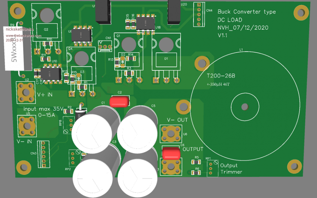 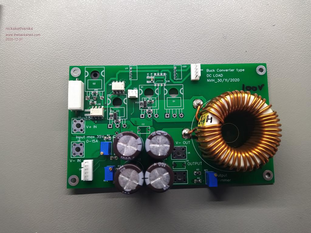 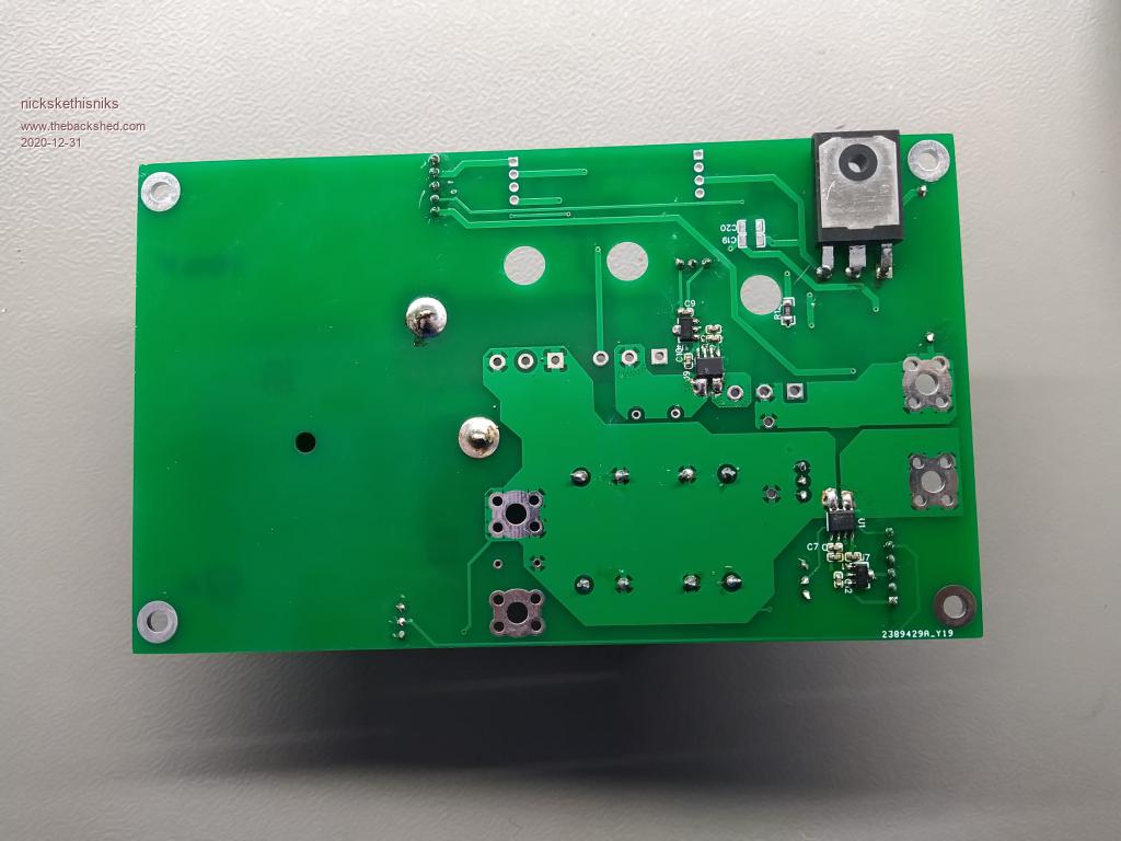 This takes me to board 2 where the galvanic isolation takes place. This board has a push pull circuit for driving the transformer, I intended to use 50khz, but it�s switching around 23khz now, that way I have better switching transitions. Then there is a bridge rectifier, there are some inductors between the rectifier and output capacitors. There is a place to add an inductor in the pushpull stage to experiment with. �Next version could be with an H-bridge to maximize the transformer core. This board has also in and/output current and voltage measurements, temperature thermistors could also be populated. �Since I want it 100% isolated, the output voltage can be measured with an isolated opamp or measured through a sensing winding on the transformer. 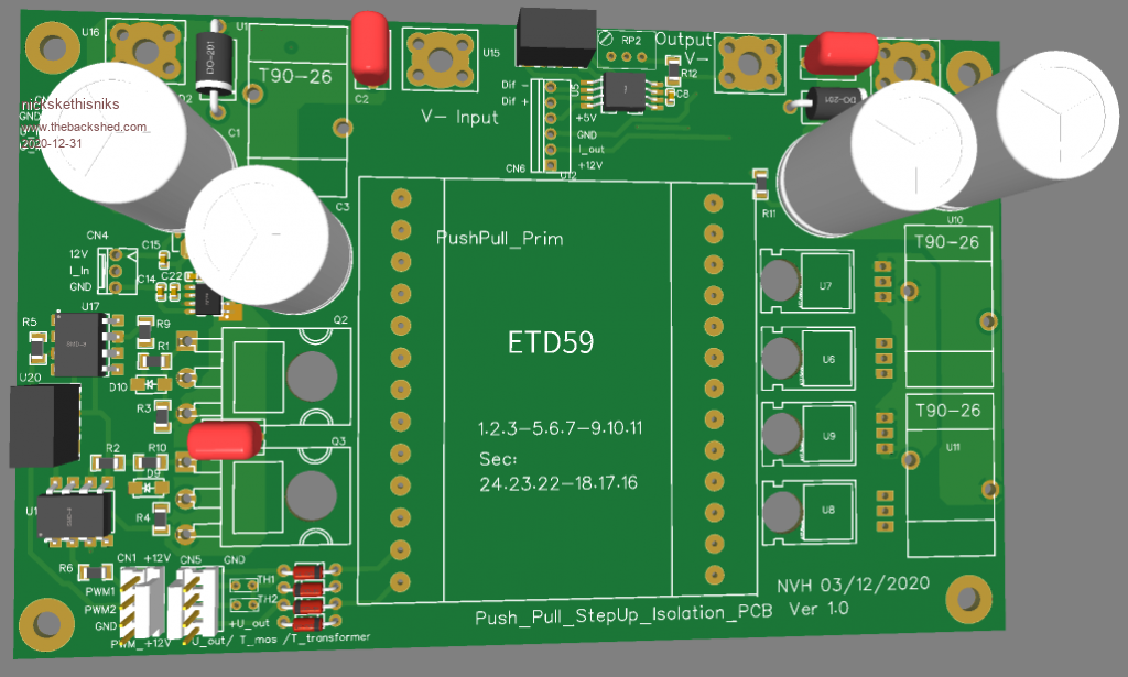 Most critical power parts I used are, IRFP4468/IRFP4110 mosfets, FOD3182 drivers, ETD59 core, T200-26B, 30CPQ100 and 16CTQ100 diodes, acs712 . For the �brain� board I�m somewhat stuck in experimental phase. I first tried MC33025 pwm ic, but it wasn�t really suitable to use it for a buck controller so I eventually switched to a better documented TL494 pwm controller that is working really well in CC mode. I think I will add CV too so I can also make it a battery charger if I want. The TL494 will get the reference signals from a dac, I think I will use a PCF7578, can�t hurt to have some spare dac outputs. �I�ve used pcf8591 in my test setup but it looked I had to load the output of the dac otherwise it went to 5V on startup instead of 0V. �There was a voltage follower behind it, the dac had only 8 bits output but it actually worked pretty fine. The concept was tested on smaller scale with just the buck converter and a 13 to 15 ratio push pull stage. So 40V went in and +/-40V went out to the input of the buck converter again. With about 3 amps flowing in to the buck converter the circuit could recuperate 2,8amps, only 200mA was needed from an auxilary suppply. � Today I tested an 110Vdc to 24Vdc power supply at work and I could test the circuit to 13A, with a 1/6 transformer I was able to put back the energy with around 90% efficiency. With the same circuit I was able to test a 110Vdc to 48Vdc supply with 10A load, and put back energy with 85% efficiency. Verry cool! I�m planning to use a manual mode were I could adjust some parameters with a potentiometer and maybe serial mode, where the nano receives some serial commando�s from a rpi with touch screen. It's possible I will use a RS485/422 interface or can interface, I want to learn more of this kind of interfaces next year, I will see how far I'll get with that. I will have a lot of analog signals to process, should I run all the signals through a voltage follower circuit and filter first before going in to an analog multiplexer (cd4051)and then too the nano? Some more critical measurements will go straight to analog pins of the nano. I�m planning to put the pwm controller ic�s to the separate brainbord, or should I better place them on the powerboards? I will add more pictures and schematics in the coming period when I get further with this project. Input and tips are always welcome and appreciated even more if they are exposing some weak, bad points in the design, always want to learn more. I hope I can finish this project next year. Edited 2020-12-31 06:57 by nickskethisniks |
||||
| Warpspeed Guru Joined: 09/08/2007 Location: AustraliaPosts: 4406 |
A really interesting project, I will be watching this with great interest. Ninety percent energy recovery is pretty good, especially for two stages, and I don't think you will be able do much better than that. Cheers, �Tony. |
||||
| wiseguy Guru Joined: 21/06/2018 Location: AustraliaPosts: 990 |
Hi Nicks - an interesting proposition and whilst it sounds feasible when the battery is connected, consider the following scenario. We start the round robin system going & we draw 1.9kW from the 48V battery and are putting back into the 48V battery 1.8kW, about 95% efficient. So now we connect a power supply to the network that can supply 48V @ 120W which more than makes up for the 100W of loss. Now we disconnect the battery just leaving the 120W power supply connected & running. So what happens? do we still have 1.8kW circulating with just the 120W loss compensating supply connected ? It hurts my head to believe that this can work - it sounds too much like almost perpetual motion lol but in theory it might ? �Gut feeling says its a long shot - either way I look forward to the answer. PS: Happy New year all ! Edited 2020-12-31 15:24 by wiseguy If at first you dont succeed, I suggest you avoid sky diving.... Cheers Mike |
||||
| Warpspeed Guru Joined: 09/08/2007 Location: AustraliaPosts: 4406 |
Should work Mike. Its like running a hose into a bucket that has a hole. The bucket stays full. Cheers, �Tony. |
||||
| wiseguy Guru Joined: 21/06/2018 Location: AustraliaPosts: 990 |
Hi Tony, I'm not sure the bucket analogy is quite correct. If we deliver water at the same rate as it leaks from the hole we will never increase the level in the bucket. but if we increase the flow in slightly more than the hole loses then the bucket will eventually fill. With the electronic equivalent if we make up for 100W of losses and add an extra 20W then in my mind only the extra 20W circulates & recirculates through the loop, but I cant see it amplifying itself as in the bucket filling and becoming for example 1.8kW. That is why in my initial observation I included a battery that I see as fundamental in supplying the initial extra energy required to achieve the 1.8kW before the aim of hopefully becoming self sustaining after the battery is removed. Am I looking at this all wrong & missing something obvious ? Edited 2021-01-02 09:15 by wiseguy If at first you dont succeed, I suggest you avoid sky diving.... Cheers Mike |
||||
| Warpspeed Guru Joined: 09/08/2007 Location: AustraliaPosts: 4406 |
Some time ago I explained how to build an inductor (choke) tester where current was ramped up during a charging cycle to some high peak value of many tens of amps in order to investigate the saturation characteristics of the inductor under test. That was followed by a discharge cycle where the stored energy in the inductor, or almost all of it is returned to a large capacitor on the dc supply rail. Only a relatively small amount of makeup energy from a dc bench power supply is required to keep the system cycling. Its possible to see current peaks of fifty amps or more in the inductor, but only two amps of makeup energy required to do it. There is a huge amount of stored and circulating energy, and if losses are kept reasonably low, very little external power is required to run it. Quite a few have been built since, and they work fine. Here is one built by Solar Mike: https://www.thebackshed.com/forum/ViewTopic.php?FID=4&TID=9632 Cheers, �Tony. |
||||
| wiseguy Guru Joined: 21/06/2018 Location: AustraliaPosts: 990 |
I built one ages ago Tony - based on your original thread (thank you !) and I know they work. I think we do concur to a degree, I see the storage of the large capacitor equaling the battery. Something had to provide extra additional (peak) energy other than the loss compensating power supply before we can recover it. If at first you dont succeed, I suggest you avoid sky diving.... Cheers Mike |
||||
| wiseguy Guru Joined: 21/06/2018 Location: AustraliaPosts: 990 |
Nicks can we have an update to this project it was an interesting concept, what was the outcome ? I recently noticed on your PCB, there are thermal reliefs that are showing on the high current Mosfets and diodes. In my experience they can create hot spots and for extreme currents become open circuit. It becomes much worse when an adjacent part or track causes the reduction loss of some thermal reliefs. In worst case there might be only one or two small PCB connections left instead of the 4 radial connections to carry all the current. For all high current connection (including capacitors) I recommend always using direct connection to ground planes with no thermal reliefs at all. Edited 2022-01-30 10:06 by wiseguy If at first you dont succeed, I suggest you avoid sky diving.... Cheers Mike |
||||
| Murphy's friend Guru Joined: 04/10/2019 Location: AustraliaPosts: 580 |
Yes, good point but doing without thermal reliefs on large ground planes requires a rather big soldering iron to do a quick & decent solder joint with large capacitors, to avoid cooking them. For that application I use octogonal pads instead, this gives me 8 thermal reliefs and I never had a problem with local hot spots doing damage. |
||||
