
|
|
Forum Index : Electronics : Driving multiple LEDs from 4000 series logic
| Author | Message | ||||
| thwill Guru Joined: 16/09/2019 Location: United KingdomPosts: 3833 |
Hi folks, As some of you know I'm a programmer with minimal electronics ability; though time permitting I'm trying to remedy that, alas more thorough reading than practice. I have a lot of jelly bean 4000 series logic chips (don't ask why, just assume I chose poorly). My question is how do l drive multiple LEDs from one of their outputs as they have very low source/sink current? I know (or can read) how to do this by using their output to drive a discrete transistor, but presumably there must also be both era appropriate and modern equivalent ICs for the task? You don't need to go into detail initially unless you want to, just a few pointers to aid my failing google-fu will hopefully suffice. Thanks, Tom Game*Mite, CMM2 Welcome Tape, Creaky old text adventures |
||||
TassyJim Guru Joined: 07/08/2011 Location: AustraliaPosts: 5886 |
The ULN2803A device is a high-voltage, high-current (Single Output) Darlington transistor array. The device consists of eight NPN Darlington pairs that feature high-voltage outputs with common-cathode clamp diodes for switching inductive loads. The collector-current rating of each Darlington pair is 500 mA. The Darlington pairs may be connected in parallel for higher current capability. VK7JH MMedit ┬Ā MMBasic Help |
||||
| Warpspeed Guru Joined: 09/08/2007 Location: AustraliaPosts: 4406 |
Jim is spot on, the ULN2803A is the device of choice. Logic high on the respective input turns it on, which pulls the output down logic low. There is also the UDN2982A. Logic high on the input turns it on, which drives the output logic high up to the power supply rail. This can sometimes be useful when multiplexing very large LED arrays. Cheers, ĀTony. |
||||
| thwill Guru Joined: 16/09/2019 Location: United KingdomPosts: 3833 |
@TassyJim, and @Warpspeed, This calls back to one of my earliest posts http://www.thebackshed.com/forum/ViewTopic.php?TID=11957 Where the answers given for what I now recognise as basically the same questions were slightly different: ULN2801(A) and UDN2981(A). I know the answer lies in the subtle details of the datasheets but I still lack the understanding to read these, e.g. Where does https://www.soemtron.org/downloads/disposals/uln28012805.pdf say how much current can be sourced/sinked ? Call me lazy (I am where I can manage it) but I guess what I really want is a simple answer as to what I should stock up with and then I'll start tinkering to see what smokes. I'll be driving them from 'mites and Arduinos if that matters. Best wishes, Tom Game*Mite, CMM2 Welcome Tape, Creaky old text adventures |
||||
| Warpspeed Guru Joined: 09/08/2007 Location: AustraliaPosts: 4406 |
I created a long and detailed reply, but could not post it. Received an error message: As I have absolutely no idea what that means I am unable to reply to your question. Cheers, ĀTony. |
||||
| thwill Guru Joined: 16/09/2019 Location: United KingdomPosts: 3833 |
In the event your reply wasn't completely lost when the forum crapped out I've PM'd you my email address if you'd consider sending me it directly. Best wishes, Tom Game*Mite, CMM2 Welcome Tape, Creaky old text adventures |
||||
| lizby Guru Joined: 17/05/2016 Location: United StatesPosts: 3010 |
The first question might be, which LEDs? With the proper resistors, you can, of course, drive indicator LEDs directly from micromite pins. 12V LED modules can be driven using MOSFETs (including dimming). By the way, if you are worried about releasing smoke, you might want to use something less $$$ than the CMM or CMM2, like BigMic's MuPv3 (sold, I think, by WhiteWizzard at micromite.org if he's not too busy assembling and shipping CMM2s), or with a longer lead time, Armmite F4s: https://www.aliexpress.com/item/32977663446.html Or just a PIC32MX170 and a capacitor on a breadboard. ~ Edited 2021-01-05 07:19 by lizby PicoMite, Armmite F4, SensorKits, MMBasic Hardware, Games, etc. on fruitoftheshed |
||||
| Warpspeed Guru Joined: 09/08/2007 Location: AustraliaPosts: 4406 |
Sorry Tom the whole thing is gone. Basically the data sheet tells you that there are five different part numbers for chips that are functionally the same. The differences have to do with the type of logic family you plan to drive the chip with. That could be TTL running at 5v, or CMOS running from 5v up to 15v or more. These are pretty old chips now, but still very useful and readily available. In theory there should probably be a 3v CMOS sixth version, but that never happened. The two most useful are the 2803 and 2801. For 4000 CMOS stick with the 2803 as suggested by Jim. The 2801 will work with 4000 CMOS but it will severely load the driver and the logic levels will not be able to reach 5v in the logic high state. That only matters if you need that logic level to drive other 4000 CMOS chips as well as the 2801. None of these chips were made to work from 3v CMOS logic levels, but the 2801 probably will, and might be your best bet if playing with the more recent 3v microcontrollers. The ULN series of chips are linear devices (L = linear) and the power output in the linear region is very limited. For lamp dimming, motor speed control, or very fast pwm, these devices tend to burn up. One watt max for one output only, or 2.25 watts for all the devices. Its not a matter of current rating, but heat. Driven from a digital on/off logic source, the maximum current from only one output working is 500 mA. If all the outputs are driving loads simultaneously, again its the heat generated within the chip that will be the problem. No simple answer to that as it involves a lot of different factors such as how the chip is driven, the supply voltage, nature of the loads, and how many loads are on together. Basically you can just put your finger on the chip. If it seems to be getting far too hot, it probably is. Edited 2021-01-05 07:30 by Warpspeed Cheers, ĀTony. |
||||
| thwill Guru Joined: 16/09/2019 Location: United KingdomPosts: 3833 |
No worries Tony, thanks for the practical advice, I've ordered some ULN2803A and UDN2982A for my stocks. Tom Game*Mite, CMM2 Welcome Tape, Creaky old text adventures |
||||
| thwill Guru Joined: 16/09/2019 Location: United KingdomPosts: 3833 |
Thanks Lizby, I'm just playing, thought I would try using some 4000 series shift registers to extend the IO from an arduino nano and drive my hand soldered LED matrix. Basically an extension of stuff I did using the CMM1 before I was distracted by the arrival of the CMM2. https://youtu.be/iwy1vCu-SLg https://youtu.be/bI9LFztEO0c Best wishes, Tom Game*Mite, CMM2 Welcome Tape, Creaky old text adventures |
||||
| Warpspeed Guru Joined: 09/08/2007 Location: AustraliaPosts: 4406 |
Those red LEDs would look a lot nicer if you used a red plastic light filter. It reduces glare and improves the contrast. Without any filter 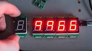 With a filter.  Edited 2021-01-05 11:30 by Warpspeed Cheers, ĀTony. |
||||
| thwill Guru Joined: 16/09/2019 Location: United KingdomPosts: 3833 |
Thanks for the suggestion Tony. The phone camera greatly exaggerates the glare, and like I said I'm just playing so it doesn't matter to me anyway. Tom Game*Mite, CMM2 Welcome Tape, Creaky old text adventures |
||||
