Notice. New forum software under development. It's going to miss a few functions and look a bit ugly for a while, but I'm working on it full time now as the old forum was too unstable. Couple days, all good. If you notice any issues, please contact me.
BenandAmber Guru Joined: 16/02/2019 Location: United StatesPosts: 961
Posted: 06:55pm 25 Oct 2021
Copy link to clipboard
Print this post
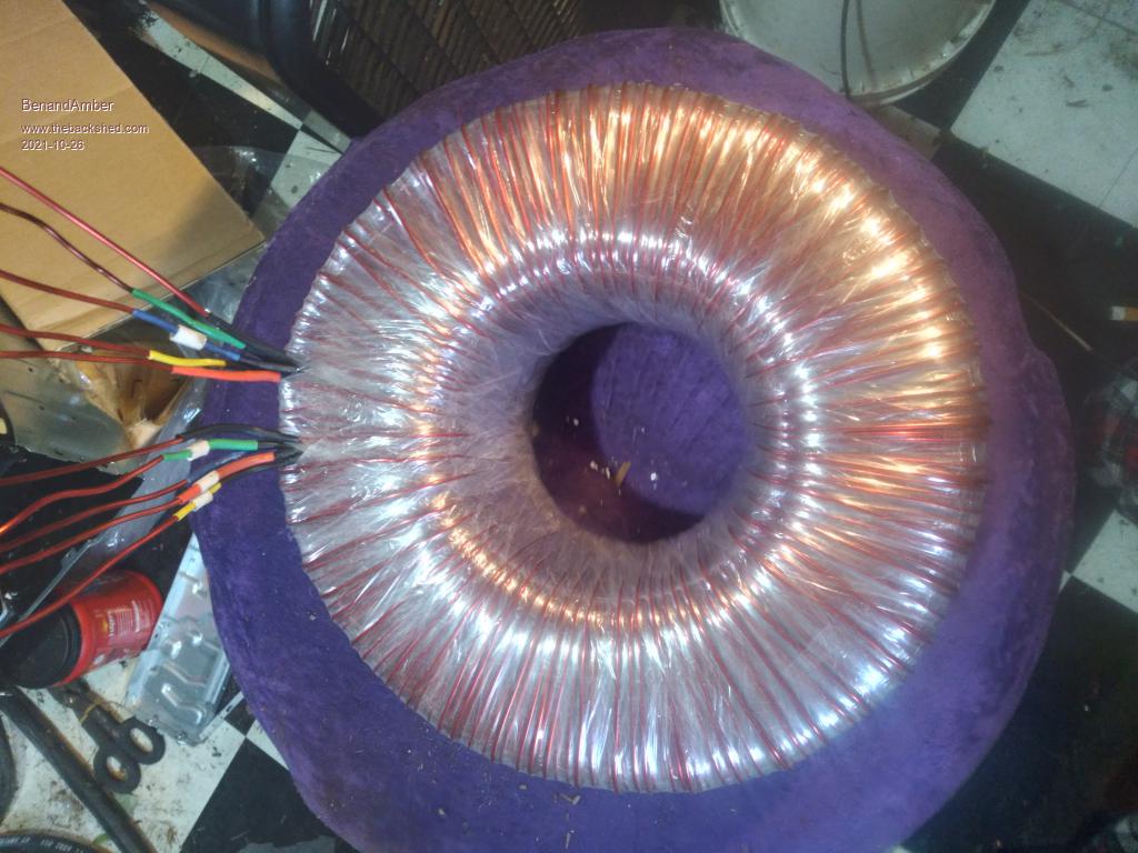
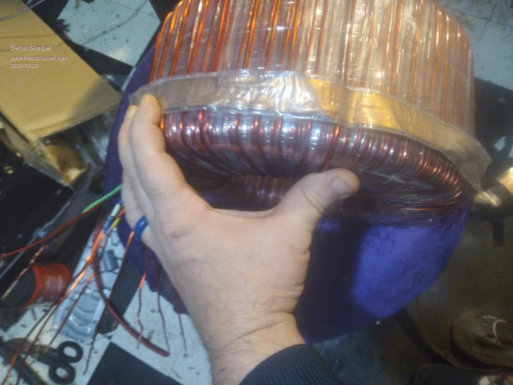
I have made a little progress on my 70 pound core
I am hoping to get 10 12 gauge windings on it but like always that hole just keeps on getting smaller
I spaced the windings so there is a few mm in between them so no wire touches I also used several layers of tape before winding over any winding
I have pulled the wire really tight and the tape stretched tight
That along with warpspeeds way to get perfect amount of turns will make it silent and a very low idle
I could have used reg bare wire The way I done it I don't know if this helps anything The enameled wire I used is new I do think it will be tougher
I am thinking about putting three in parallel like in pics over high side under low side and running a wire from them to case of inverter
I am also thinking about putting a really thick something to space the high and low side out frome each other
So the capacitance coupling will be less maybe
I really don't know if these two things will hurt or help
Please comment your opinions or facts
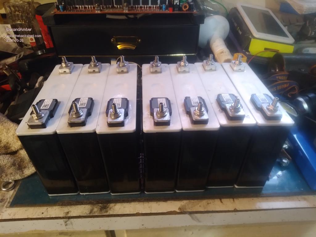
I am building a 24 volt battery for a 2000 watt smart ups I have been using for a few years now
I drilled and taped those batteries so don't look to close lol I should have used my drill press
Heath issues keeps me from making any good progress but I will get there maybe
I hope and pray you guys down under are doing well God bless you guys Edited 2021-10-26 05:16 by BenandAmberbe warned i am good parrot but Dumber than a box of rocks
Godoh Guru Joined: 26/09/2020 Location: AustraliaPosts: 531
Posted: 07:06am 26 Oct 2021
Copy link to clipboard
Print this post
Using enamelled magnet wire is a much better way to go than using bare copper wire. Enamelled wire stands up well in electric motors, after winding the motor the whole thing is usually dipped in varnish and allowed to soak before being baked in an oven to dry. Or alternately the windings are heated up and epoxy resin is poured over the windings if the motor is an urgent job that can't wait to be cooked.
The varnish binds the whole thing together and helps prevent vibration from wearing the enamel off and causing shorts. Many new motors coming out of asia are only shown the varnish tank but still manage to last quite a long time.
Pete
BenandAmber Guru Joined: 16/02/2019 Location: United StatesPosts: 961
Posted: 09:41pm 27 Oct 2021
Copy link to clipboard
Print this post
Thanks for the info Pete
I used new enameled wire on the tranny I also spaced the wire thinking it may make it better
Likely a wast of time though
Do you have any clue what the strip of insulated thin but wide copper will do in-between the high and low side
Thanks again for the infobe warned i am good parrot but Dumber than a box of rocks
Godoh Guru Joined: 26/09/2020 Location: AustraliaPosts: 531
Posted: 10:32pm 27 Oct 2021
Copy link to clipboard
Print this post
I don't know for sure what the copper strip is about. My best guess would be that it is there to prevent the high voltage winding from being damaged when the much thicker low voltage winding is wound over the top. Often when we used to rewind transformers or coils the windings would slip down the side or cross over, we would put a piece of insulation over the windings so that we could get the layers of the windings back to neat full layer windings. If the strip were magnetic material I would say it was to cut out stray magnetic flux but copper not sure. Pete
BenandAmber Guru Joined: 16/02/2019 Location: United StatesPosts: 961
Posted: 01:14am 28 Oct 2021
Copy link to clipboard
Print this post
Pete thanks for you input
I have seen a few trannys have the flat wide copper winding when unwinding a tranny to rewind for a home made inverter
I think that weird winding probably went to the case of the machine the tranny came out of
I am thinking about trying it on the 70 pound core tranny in the pic
I think it would help with interference between high and low windings also
It could be possible it could help other things
Maybe theses things has not been previously considered because there not a big problem
Like I have read that capacitance coupling can be a problem In the warpspeed inverter
I think warp and mark fixed this by putting a spacer in between low and high side windings
But I am not for sure I don't think there was a update after a while of testing
So this same thing could be happening in high speed switching inverters like nano gs 002 pj and others
Don't get me wrong I am MORE than happy with the many trannys I have rewound
I am very grateful for the good people on here and a few others that took the time to teach me
Trust me when I say it not a easy thing to do
I am just always looking and testing to improve inverters in any way I can
So I am looking for advice
Is the thin wide copper wound around the out side in between and spacing the low and high good things to try and test
And is there other things I should try in this process of improving trannys
I found already found out warpspeed way to wind a tranny is the best way
Not only to get the perfect volt per turn for any core
Also the lowest possible idle current silent dependable that stand out above all others
I don't say that lightly I have and have had well over 100 tranny in last few years
I don't think warpspeed way test wrap a few more turns test again can be beat
Another I know warp tried to tell me many times i didn't get until running across it myself is
There is no definite wattage rating for a core
It comes down to can you get rid of the heat that determines core size
Let's say your normal usage is under 3000 watts
But a few times a day for short periods of time It goes up to 4000 watts
Maybe this only happens when you heat water or run microwave both of which would be under 30 minutes
A used 3000 watt continuous core will work great in the above example
When rewinding just wind the extra copper to low and high side for 4k instead of 3k
But much better if you wind all that will fit and a bolt still fit through for bolting it down!!
In the above case the core will have time to cool off before the extra 1000 watts will be needed again
Most if not all big loads in a normal home kick on and off and are not constantly on
A newbie should keep this in mind
Of course you should and its best practice to over size a inverter at lest by a 3rd
This stuff is common sense to you Pete Also to the guys on here But to the newbie to this stuff it is not
So I write it again hoping to help someone
When a newbie is scrounging up a used tranny this info makes it easier to find a cheap used tranny to use on a build
And the tranny is the hardest part if using one of the pre made boards with all the components on them
Sorry I got off topic Pete And I do appreciate your timebe warned i am good parrot but Dumber than a box of rocks
InPhase Senior Member Joined: 15/12/2020 Location: United StatesPosts: 178
Posted: 03:31am 28 Oct 2021
Copy link to clipboard
Print this post
The copper foil reduces the capacitive coupling of high frequency noise between the windings. It doesn't affect the magnetic coupling between them.
tinyt Guru Joined: 12/11/2017 Location: United StatesPosts: 441
Posted: 12:35pm 28 Oct 2021
Copy link to clipboard
Print this post
Just make sure you don't created shorted turns when putting on the copper foil.