
|
|
Forum Index : Electronics : Baby 72v off grid system
| Page 1 of 2 |
|||||
| Author | Message | ||||
| oreo Senior Member Joined: 11/12/2020 Location: CanadaPosts: 133 |
So, prior to seeing this forum, I decided I wanted to build a small off grid system, thinking it might lead to something larger in the future. I thank the people who have posted the wealth of knowledge that is contained in this forum. I am sure I have/will blow up less stuff, with the work people have done and documented here. Solar Panels So I am using just 4 right now, fastened to the side of the house. The corners at the top of each cell, are reinforced with a 3x3" L shaped aluminum bracket, glued in with JB weld. Then 2.5" door hinges were used to fasten the tops to the wall. I then made struts of various lengths, so I can set the angle of the cells. In my area the sun angle varies from 22-70D. The below pic was taken prior to running the wire/conduit. 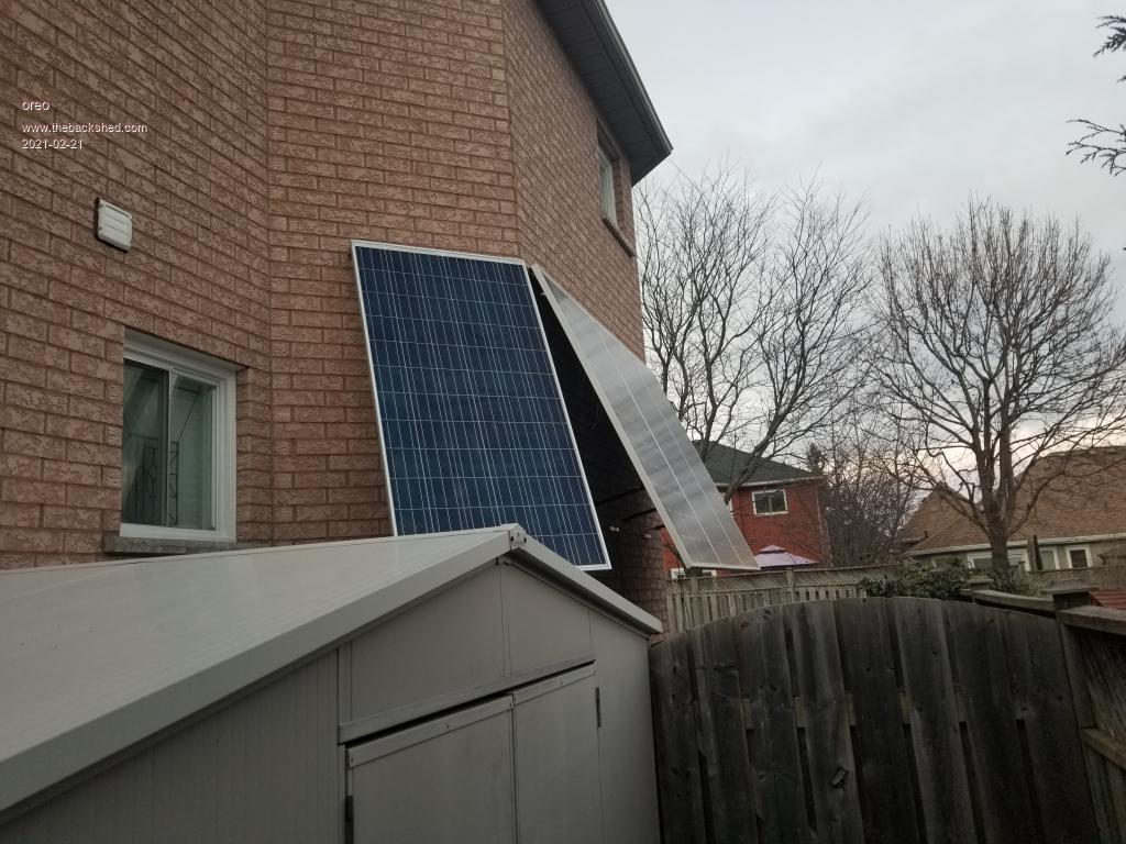 It's winter here, and on a good day I can only collect about 4.5kw. Most days are much lower. Right now I have these cells in serial/parallel, going through a linear regulator into the battery. The battery voltage ranges from 72-81v, while the max power voltage of the cells is quoted as 76v. I have tested the cells at different light intensities, and always find I get the maximum power at this voltage. Under what conditions would I find that this maximum power point voltage would change? Right now I calculate I am only losing about 5% of input power because of not being at the ideal voltage, so am not sure there is much point in doing a MPPT charger for this system. Greg |
||||
| oreo Senior Member Joined: 11/12/2020 Location: CanadaPosts: 133 |
Right now, I have everything mounted on a couple of mover dollies. I am ready to move the inverter into it's own case now. 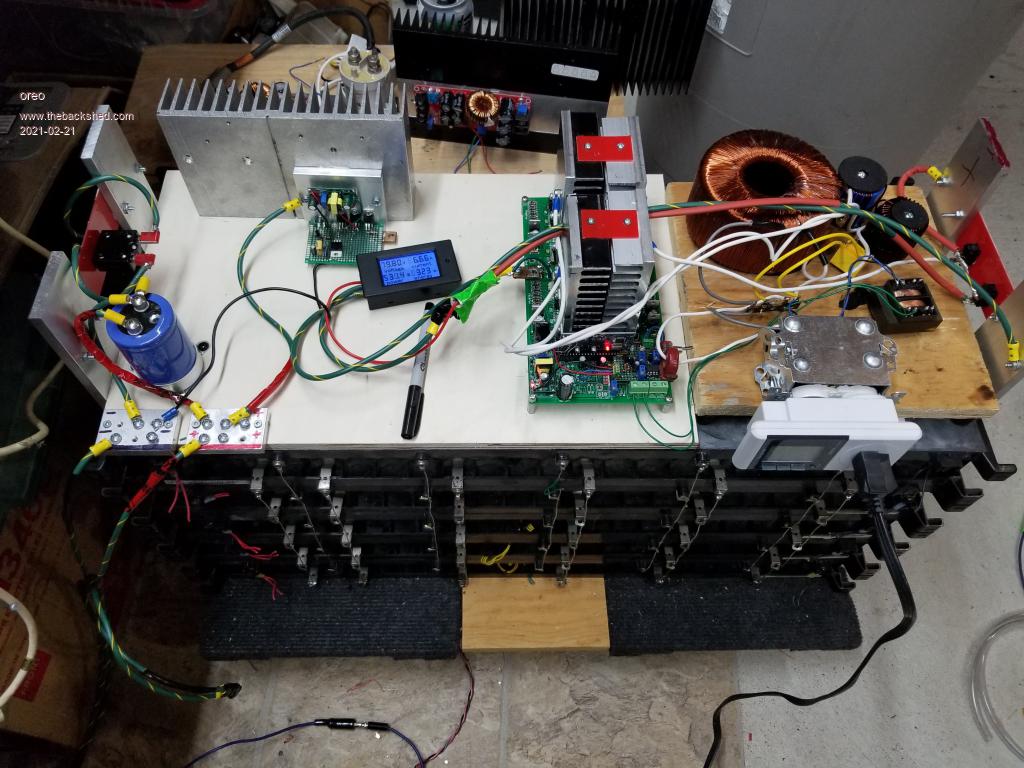 Since I don't have a MPPT charger, I am just using a linear charger, set to 81.4v or just under 3.4v per cell. The batteries are rated at a float charge voltage of 3.45v, but I am finding the battery capacity to be pretty good at 3.4v. Here is a link to where I found the basic circuit. High voltage linear regulator I added an isolated 12v dc-dc converter to this design, so I could get low Fet on resistance, when the output voltage was close to the input voltage. 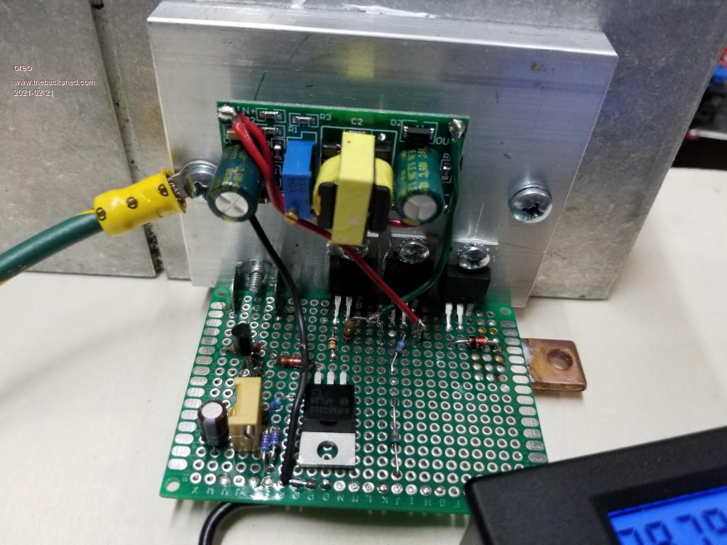 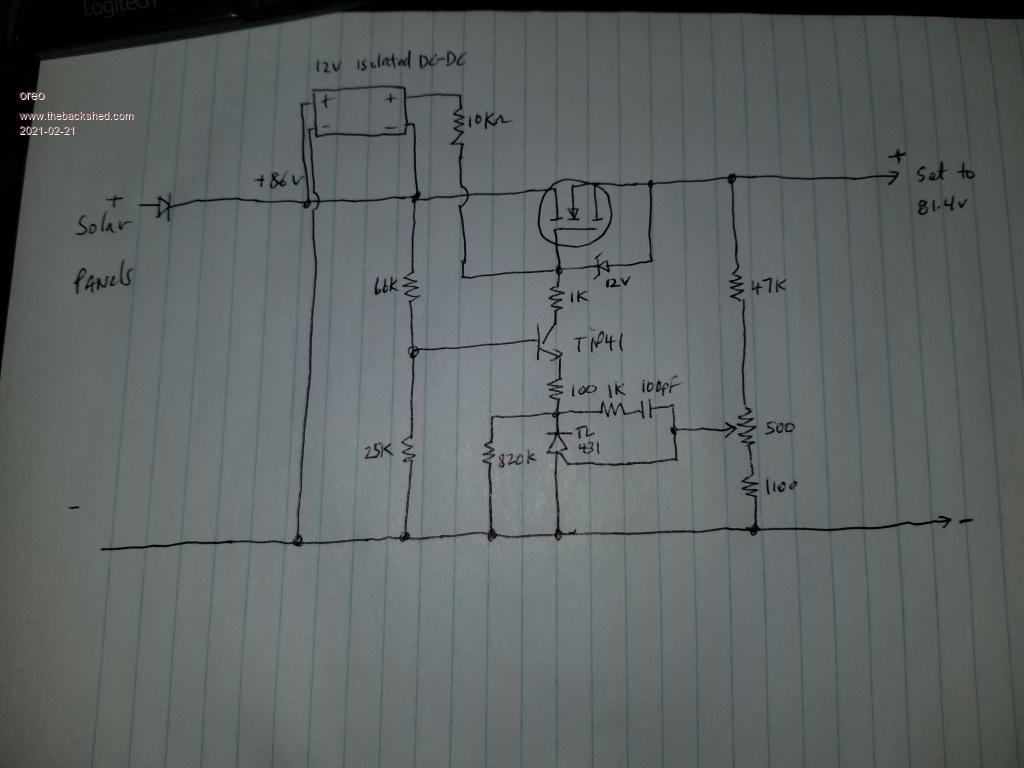 I am happy with how this works, however I still need to add battery cell balancing and an undervoltage/overvoltage disconnect for the battery. Currently the battery is pretty well balanced (within 2mV at both low and full charge), however I need protection if something goes wrong. Greg |
||||
| Warpspeed Guru Joined: 09/08/2007 Location: AustraliaPosts: 4406 |
Excellent !! It does vary very slightly with solar intensity and temperature, but not by enough to even think about. Matching the panels to the battery is a really smart move, you will get excellent all around efficiency with a very simple low cost system that has very little that can go wrong. Cheers, �Tony. |
||||
| oreo Senior Member Joined: 11/12/2020 Location: CanadaPosts: 133 |
Tony -thanks for the encouragement and the info on MPPT voltage. I wish I could say that I matched the panels to the battery. I decided to go 72v rather than 48v, for other reasons. 1. My batteries are 36v, and it would be a lot of work to break them apart. 2. Primary circuit will have less current with 72v, and I have access to lots of 200v fets. 3. I have access to discarded transformers which are 110vct, which would be pretty easy to modify for a 72v system. After I decided this, I realized that if I put the solar cells in series/parallel the voltages were close. I initially was planning on putting all the solar cells in parallel, and using an DC-DC upconverter. So I lucked out. Prior to finding this forum, I saw the below video which has a zip file in the text, with gerbers for the PCB. 48v Inverter So I ordered 5 of these boards, and so far have built up 1. The board design is pretty good, and most of the components fit into their holes. It uses totem pole drivers, and a SMT uP, which monitors input voltages (I didn't use the uP) I made some changes, mostly based on Tinkers thread on how to modify the EGS002 board, and an attempt to use components on hand. I added an undervoltage cut out, and a provision for going slightly lower on the undervoltage, if the circuit was drawing a lot of current from the battery. I am just using 3 IRFB4227PBF per leg, since I don't plan on supporting more than 1kw with this board. (2 transformers) In this picture, I have a DC-DC converter, for a 48v system. 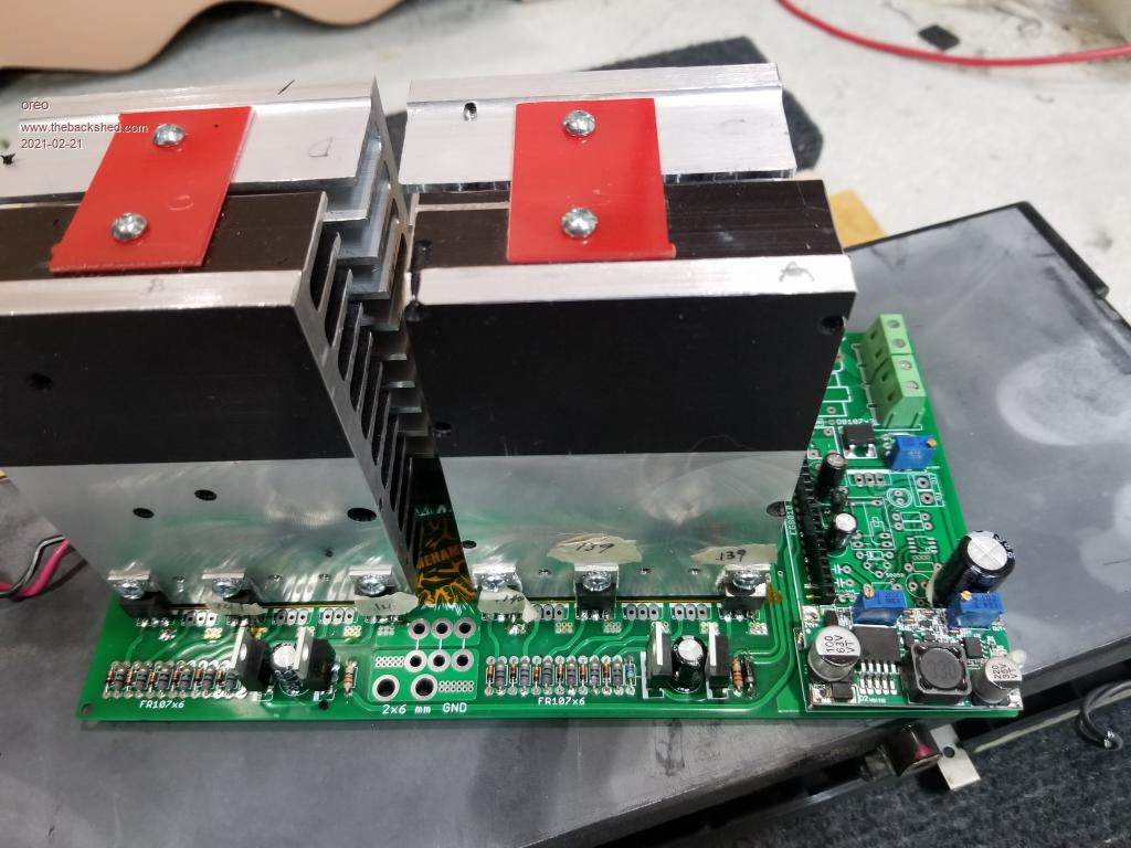 Here I have a DC-DC converter which supports in excess of 200v. 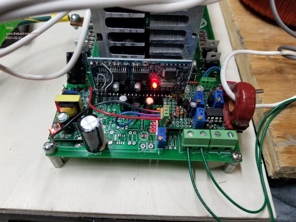 It was a little painful building up the small point to point wiring board. I may end up doing a pcb if I like the way it works long term. Greg |
||||
| oreo Senior Member Joined: 11/12/2020 Location: CanadaPosts: 133 |
I have access to lots of inductors on boards which end up in recycling. Problem is, that all of them are not huge current. If I ever do a high power inverter, I am going to need to purchase some cores. To measure saturation, I used a little spot welder that I had purchased back when I thought I might be building a battery pack. 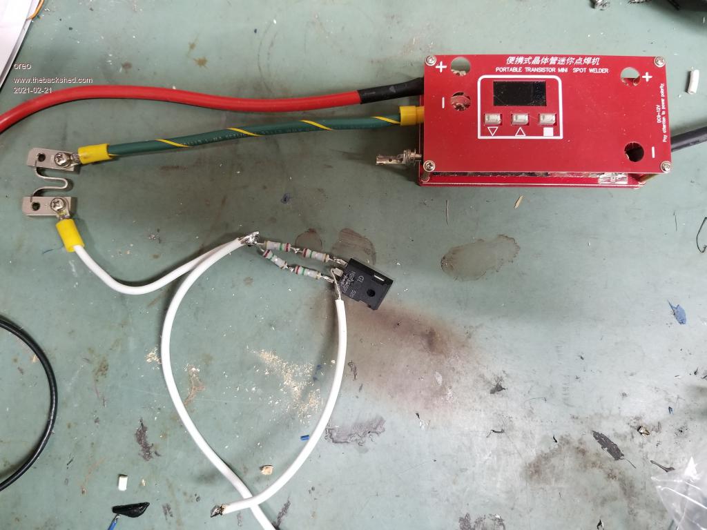 Using this, a storage scope and a 12v battery with lots of output current, showed that a 3 stacked choke had the best performance, without rewinding. The choke is ~300uH (yes, higher than it needs to be) and on the blue curve below, each 50mV represents 15 amps. So it starts to saturate at 15A, but doesn't get into real trouble until about 30A. At 30A, it is still acting like a 85uH inductor. So I am using 2 of these in parallel. At 30A, they would probably melt. 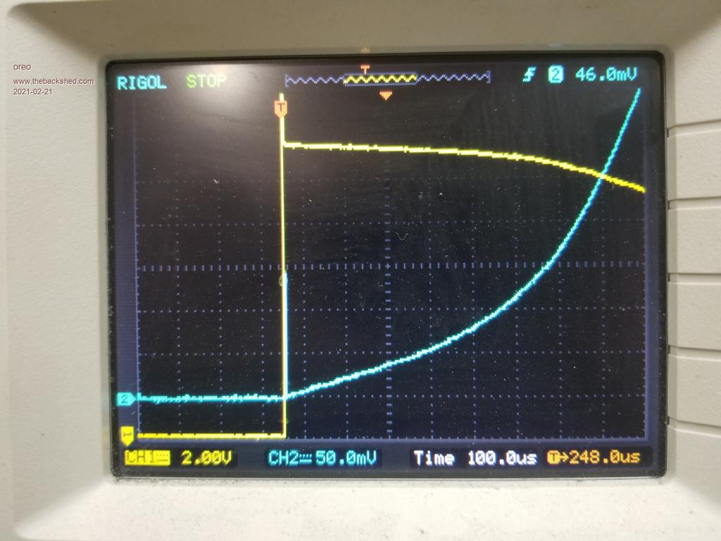 Using Tony's method of using a 10k series resistor to determine capacitance value yielded some strange results. The test suggested that I use an very low value of capacitance (.40uF) to obtain the peak at 90Hz. I ran the procedure twice with a week in between just to confirm the results. When I tried using this value, it did not filter out all the hash. So I ended up using 1.2uF, which was the lowest value I could use, which gave me a clean sine wave. The sine wave on the output of the transformer looks perfect on all the loads I have thrown at it so far, but I have not put a motor on it yet. Greg |
||||
| Warpspeed Guru Joined: 09/08/2007 Location: AustraliaPosts: 4406 |
It sounds like you are getting down near 60Hz resonance with 1.2uF, which will give you the cleanest sine wave, but you may have trouble regulating the output voltage with zero load. See how that goes... Cheers, �Tony. |
||||
| InPhase Senior Member Joined: 15/12/2020 Location: United StatesPosts: 178 |
Something I don't understand about the inverter board from the video: Where does the 3.3 volts that feeds the totem poles come from? I don't see the source on the schematic. Also, how does 3.3 volts drive the mosfets into conduction? Isn't that too low, especially on the high side? |
||||
| oreo Senior Member Joined: 11/12/2020 Location: CanadaPosts: 133 |
Yes, that confused me too. For some reason, the author used a 3v3 schematic label, on a circuit which actually is 12v (fed through a diode). So the totems are driven with 12v. On the schematic, this diode is just below and to the left of the Tiny13. Some parts of the schematic are difficult to read due to idents being on top of parts. It's not ideal but workable. Yes. The required value will change when I add the additional transformer. Hopefully things will be in check at that point. Edited 2021-02-21 23:23 by oreo Greg |
||||
| oreo Senior Member Joined: 11/12/2020 Location: CanadaPosts: 133 |
I initially I thought us guys with 60hz, had a huge advantage when it comes to the transformer. To achieve the same flux density with 60hz vs 50hz, you can use less turns. Using the calculator, if I need 140 turns at 50hz to achieve 10KG, then I only need 120 turns at 60Hz. Bonus.... Well actually it turns out, not so much. Here is a loss chart, I pulled from the internet. This shows the core loss in Watts per pound. 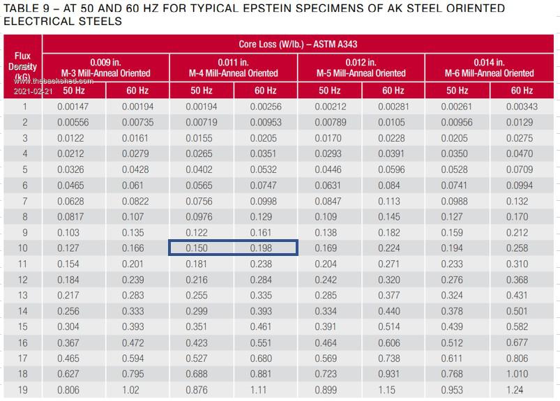 The transformer losses are greater at 60Hz than 50Hz for any given flux density. Working the numbers, if your loss goal has you using 140 turns at 50hz, then you need to use 136 turns at 60Hz, to achieve the same losses. So 60Hz is not as much as an advantage, as I was thinking. If you're buying a used transformer, then getting one out of a piece of audio gear will get you a transformer designed with lower flux density than typical. Audio consumers don't like hearing noise from their gear, so transformers are typically designed to 13-14KG. A slight advantage if you plan to use the transformer without a rewind. For now, this is what I am doing. Recently the company I am with has tossed a good number of transformers, due to excessive audible noise. I took one completely apart and unspooled the core a bit. Not too difficult. I may try to custom wind a core for my first transformer build. Another suggestion. I see some on this forum have used welding wire for at least one of the windings on their custom transformer. Keep an eye on local sales outlets like Craiglist, Facebook and Kijiji for people selling used cable. Some have cable where they have damaged the insulation, and are selling it cheap. It is easy to remove the insulation. I am going to experiment with some thin wall heat shrink to see if I can make that work. Edited 2021-02-22 00:21 by oreo Greg |
||||
| Warpspeed Guru Joined: 09/08/2007 Location: AustraliaPosts: 4406 |
The suggested design flux density for an inverter is 1 Tesla (metric) or 10,000 Gauss (Imperial). The losses will be vastly less than at the 13,000 to 14,000 Gauss for a grid operated transformer. Zero load idling current will drop to a fraction at the lower flux density. Cheers, �Tony. |
||||
| BenandAmber Guru Joined: 16/02/2019 Location: United StatesPosts: 961 |
I like the higher voltage I think it is the future Worpspeed is right "ofcourse" about the tesla and idle current I have learned so much from him and others on here I recently partly rewound a large tranny and didn't add extra turns the way worpspeed has written about I now have to unwind the low side and add more turns to both windings because of the almost 1 1/2 amp idle current My usual idle current is around or under half a amp with trannys in the 5000 to 10000 watt range That is a huge difference so the extra turns to lower the Tesla is very worthwhile Genetry solar has as5 PJ trannys for 150 bucks including shipping in most us states If you're looking for a good size Transformer to add some copper to Have a blessed day be warned i am good parrot but Dumber than a box of rocks |
||||
| oreo Senior Member Joined: 11/12/2020 Location: CanadaPosts: 133 |
Thanks. Their website says "sold out" on this transformer. Their full inverters seem to be pretty inexpensive although now I see that they can only put out about half of their rated power on a continuous basis. Yes, I agree and if I were building a 6kva transformer, it would be 10KGauss or lower, however for a 500-1000va transformer, which has a core of 6-12lb, then it's not quite so important. Here is the power draw I currently have, with my tiny toroid with a sub 7lb core. I tried removing the EI transformer, and the standby went down to 3.4w (non isolated though) BTW, I am pretty impressed with the accuracy of this wattmeter. The voltage and current measure bang on with my Fluke, even though the wattmeter shows less digits. 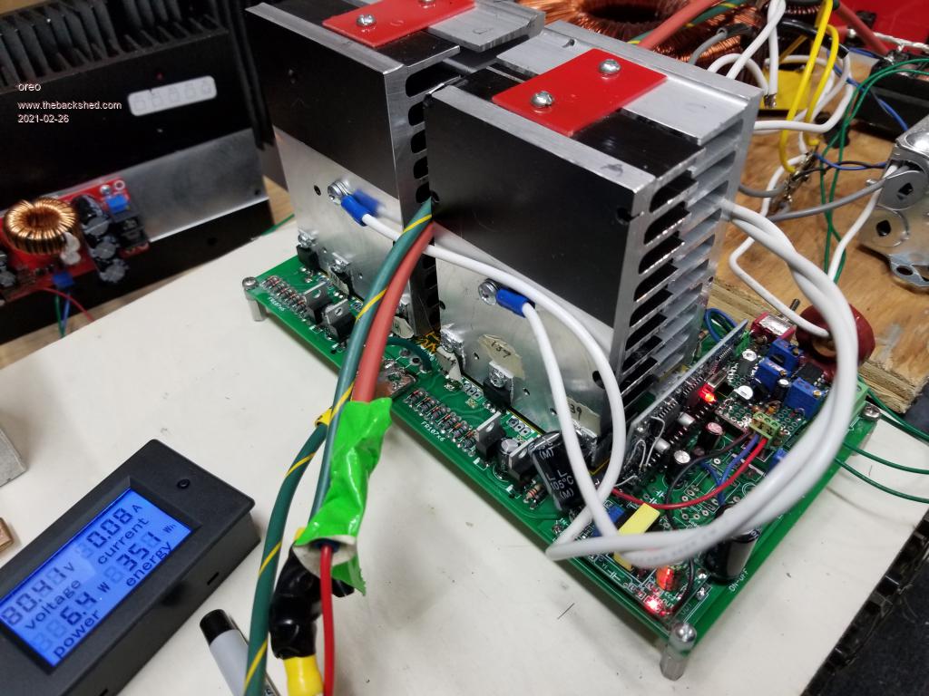 So I managed to blow up my regulated linear power supply. Don't think I have tried to run it at full output power and voltage for more than a few minutes until this project. It's old and I decided to replace it with a RD6018. An RD6018 is really a programmable buck converter, so I need something to supply it power. There are several versions with different current ratings, RD6006,RD6012 and 6018. Here is a short video, -there are lots on youtube. RD6018 Anyway, now I am looking for a power supply for this, as well as a power supply to charge my batteries off peak, when I have no sun. I have found that used server/phone power supplies are cheap and some have decently high voltages. Here is a listing of some of the models with output voltage and current. 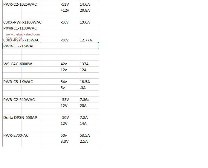 I can purchase the units up to 1kw for less that $50cad and the 2700w one for $70. If you're looking for 12v supplies, they are even cheaper with units for 10-15$ with 400-700w output. If you're looking for these, check ebay or your local buy/sell. I think I may need to trick these into outputting a voltage. Plan to pick up a couple on the weekend, so will know soon. Greg |
||||
| BenandAmber Guru Joined: 16/02/2019 Location: United StatesPosts: 961 |
there was some nice ones for 99 shiping and all on ebay no cennter tap on 240 side guy said they will do 5k when rewound if you need me to look the guy up let me know as far as i know the gs not pj will do 6k and on up to 8k i dont have one of the gs trannys but have been using everything else and i have never seen anything like it it is awesome and very tough biggest tranny i have had on it so far was 15k but soon will have a over 20k hooked up Wow that is a very low idle you have i have never seen that low of idle before best i have ever done was a little over 1/4 of a amp at 54 volts on a 2k all of my big ones are under a amp do you like that other board layout that is free on youtube from i think the same guy 102 or 103 guy mack also has a board and i know you have seen the madness board if i can help in any way would love to do so have a blessed day be warned i am good parrot but Dumber than a box of rocks |
||||
| oreo Senior Member Joined: 11/12/2020 Location: CanadaPosts: 133 |
I presume you mean this one? Transformer? Long term, I am not exactly sure yet what I want to do transformer wise. At this point, I am not ready to buy a core. Yes, this is the board I am using. I like the fact that it uses TO-220 devices, and is fairly compact. For the foreseeable future it should work well for me. Currently I am building a second unit for a buddy with a 24v system (I have 5 boards). Thanks for the offer and I feel likewise. Greg |
||||
| oreo Senior Member Joined: 11/12/2020 Location: CanadaPosts: 133 |
So I finally got the power supply together. Thank goodness for the internet, because these supplies needed specific pins shorted, before they would output any voltage. Fortunately, the fans are pretty quiet (that may change when I run the supplies hard). I am using 1 12v and 1 56v power supply for the step down power supply and have another 12v supply also wired in series so I have 80v on a separate set of binding posts to charge my battery (only 1 post installed right now). 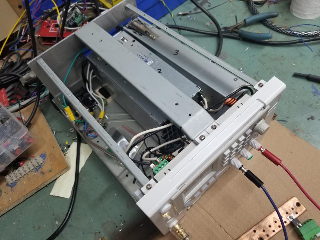 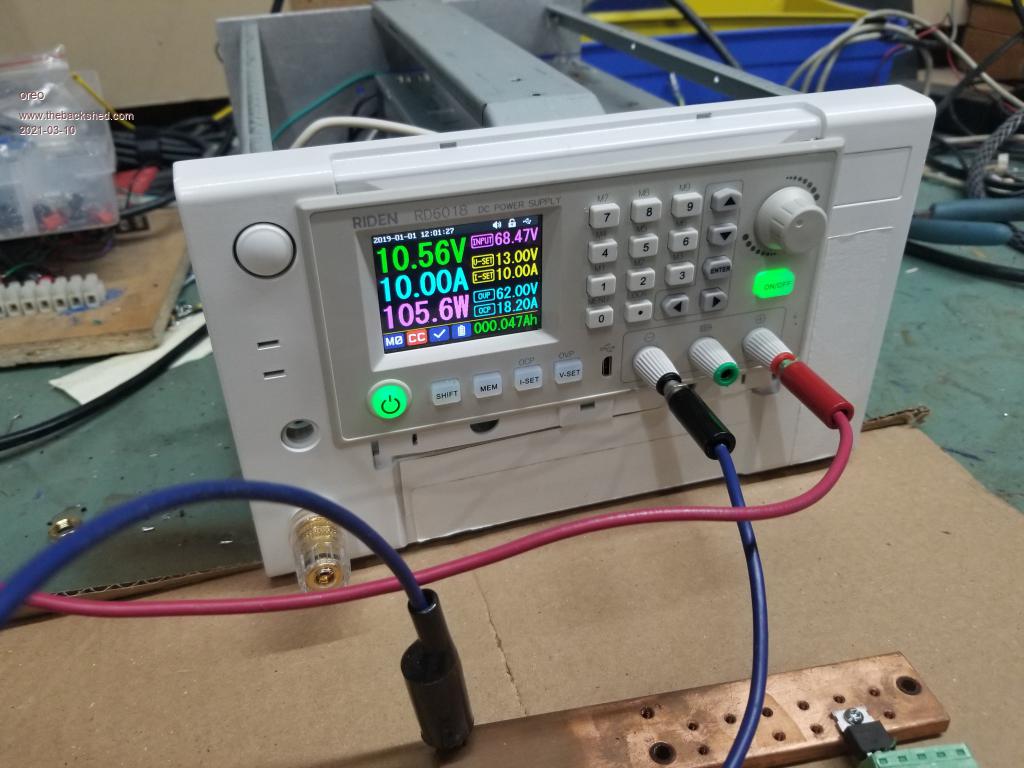 Much more convenient for testing mosfet on resistance, since the power supply maintains the correct current. The only inverter anomalies I have noticed so far, is that on occasion the voltage hunts around +- 2 volts under some loads. I am driving mostly motors, which may not be helping. Here is what the voltage and current look like when predominantly the furnace is running. (blue = current)  And when the fridge or freezer is running. 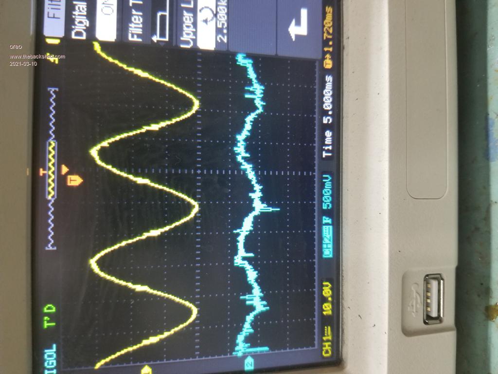 As a result, my AC wattmeter reports totally wrong numbers. Is anyone else having trouble attaching pictures? I had to keep hitting upload and eventually it would. Not sure why the last picture is rotated. I tried rotating my computer copy, and then uploading. Same result. Greg |
||||
| oreo Senior Member Joined: 11/12/2020 Location: CanadaPosts: 133 |
So the last 3 days have been unusual, in that they were completely cloudless. This allowed me to make some measurements on the output of the solar panels to understand if using the current 2P2S set up going directly into the battery, was better/worse to a 4P setup, with an DC-DC upconverter. I had purchased one of the 2400w upconverters that others on this forum had purchased, and generated a schematic for. It has a built in fan, but I ended up connecting 2 small fans which were on continuously. (about 5w) Without this, I felt it was running too hot for my tastes. So I ran the 2P2S setup for the first 2 days, logging the current and total power delivered to the battery. For both days, the daily production was pretty close to equal at 4900w total each day. I made sure to discharge the battery to the same state for the beginning of the next day. For the final day, I reconnected the solar cells to 4P and connected the up converter. I adjusted the upconverter to 82.5v output (slightly higher than the linear regulator, which is set to 81.5v) and manually adjusted the current limit, to maximum power into the battery. During some points of the day, I had to adjust the current every 10 minutes as things were changing rapidly. From 9am to 2pm, things were much more stable, and I adjusted the current every hour. The results are as such. During the early morning, till 9AM, the Up converter was better and was 120w ahead. From 9-12, the upconverter lost it's advantage and by noon was only ~80w ahead. From 12-5pm, the upconverter was significantly better and was 800w ahead by 5pm. So about 16% more power using an upconverter with MPPT. Probably do slightly better than this with an automatic circuit. I think that part of the problem is that my battery voltage is running high at the end of the day, when the solar output is dropping off. The other is that the solar panels are not all pointed in the same direction, so having them in series is limiting power. I tried setting the min operating voltage of the up converter to 34v (it's highest setting) and then doing some tests to see how well it transfers power when cycling on/off. Best guess is it is losing about 25% of the power. So a no go there. So I think I am going to add a uP and circuit to add MPPT to the upconverter. I am new to Arduino but have purchased a few bits to experiment with. Edited 2021-03-24 05:01 by oreo Greg |
||||
| Warpspeed Guru Joined: 09/08/2007 Location: AustraliaPosts: 4406 |
Mppt is definitely the way to go if you have very limited solar panels or available area to fit more. Panels are now becoming ridiculously cheap, so if you have the space, an excess of panels will always be better especially when its really dismal and cloudy. A simpler (cruder) system may not only cost less initially, but may also be more long term reliable. Cheers, �Tony. |
||||
| wiseguy Guru Joined: 21/06/2018 Location: AustraliaPosts: 1297 |
When I was bench testing my inverters on the bench and powering them from a mains input power supply, I had a similar varying of the inverter output voltage. It turned out that it was due to the fact the inverter operating frequency was slowly drifting compared to the mains frequency and my power supply had a very small amount of ripple under load. As the two frequencies drifted relative to each other there was a few volts variance at the inverter output, between when the peaks lined up and when they drifted away. It lead to a very slowly changing output voltage that for a while I was convinced it was an inverter problem - which in my case it wasn't. If you are using a cheap and nasty watt meter (the $15 - 30) blister pack cheapies some have terrible wattage behaviour and are actually showing VA not true watts. If at first you dont succeed, I suggest you avoid sky diving.... Cheers Mike |
||||
| oreo Senior Member Joined: 11/12/2020 Location: CanadaPosts: 133 |
Yes, both these statements make sense, however I can't expand the quantity of solar cells right now. Need to first show the system is reliable and does something :) Interesting inverter ripple problem. You must have a pretty strong power supply, to power your inverter. And yes I am using a cheap and nasty AC watt meter, so I am having problems with reported power not being correct. Greg |
||||
| oreo Senior Member Joined: 11/12/2020 Location: CanadaPosts: 133 |
So, I cobbled together an circuit to MPPT the upconverter. First off, I measured efficiency, which was not too bad. 36 to 78V 3.6w out 42% 18w out 88.6% 36w out 90.8% 67w out 93.6% 90-500w out ~94% 600w out 93.6% My panels will output about 1100w max, and I am guessing the efficiency is about 89% at that output. I used 1800w rated upconverters and removed the 200K resistor to +5v, and tied 4 wires back to the Arduino. 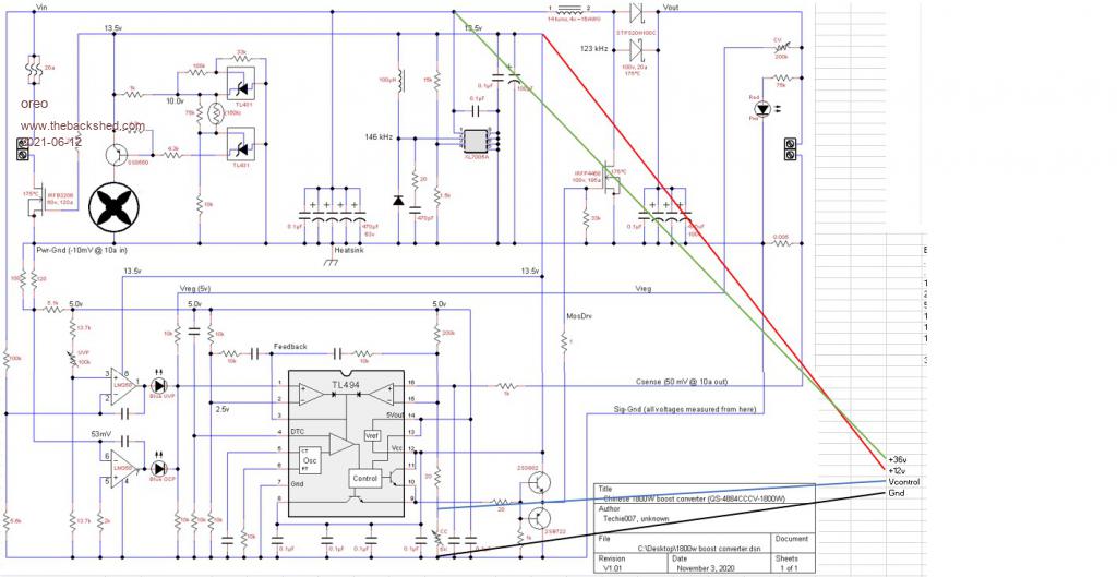 I used a MPC4725 Arduino DAC, with a voltage divider at its output to vary the voltage tied back to the current sense on the TL494 to vary the maximum current output. Basically the code tried to maintain the ideal input voltage for max power by adjusting the output current. I also had current sense on there if things looked to be working out, but I never got there. (I had to use an additional 15000uf at the upconverter input to keep the input voltage stable and probably could have used more). Below 50w, I had to use a 1v higher target voltage then ideal but I was pretty happy with how it worked. I was collecting power over a much wider period of the day and peak power was also good. Unfortunately the Upconverters kept failing. I popped one, so ordered 2 more. On the 2nd go, I made sure the unit was not running close to hot, yet it still popped the main mosfet. I have not fired up the last one yet, and may try replacing the mosfet with a NA brand part on one of the blown units. 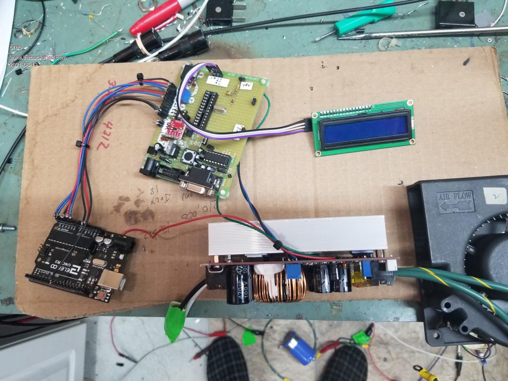 So for now, I have just inserted a 12v switching power supply in series with the solar array. This actually works pretty well, except at low power levels where the idling/low power consumption of the power supply chews up all the power. I have ordered a couple of $20usd HP 80 Titanium power supplies to experiment further with this method. Longer term, I guess I need to mount some more solar panels. The loads I have draw a steady 250w/hr, and my solar can't even provide that on a reasonable day. Also, I may be adding a bit more battery capacity. These same 36v Lifepo4 batteries are available again and are still really inexpensive. They have to be disassembled from large packs, and transported 200km, but they cost $60 cad/KWH taxes included. Technically they are EOL but still have low esr and reasonable capacity. People are reporting better numbers for this batch, compared to the last but its hard to know exactly what you will get. Edited 2021-06-12 01:45 by oreo Greg |
||||
| Page 1 of 2 |
|||||
| The Back Shed's forum code is written, and hosted, in Australia. | © JAQ Software 2026 |
