
|
|
Forum Index : Electronics : Simple mono/stereo audio mixer circuit
| Page 1 of 2 |
|||||
| Author | Message | ||||
Cyber Senior Member Joined: 13/01/2019 Location: UkrainePosts: 161 |
Hello. I want to make a very simple mono/stereo audio mixer to mix 3 inputs: - computer stereo sound card - motherboard mono speaker (pc speaker/buzzer) - external music player I plan to connect mixer output to stereo speakers with active aplifier. Use case is retro gaming. Some old games play music from soundcard, but sound effects still come from PC speaker (for example Ultima). Other games don't have music at all, so I turn on some external music. And it would be nice to hear all sounds from same speakers, and adjust volume level for each input. I found such circuit of passive mixer: http://www.therandomlab.com/2015/05/simple-passive-monostereo-to-stereo.html I would need to change one mono input to stereo input, so I would have 2 stere inputs and 1 mono input. Would it be ok for my use case? I'm open for any suggestions. Thank you! 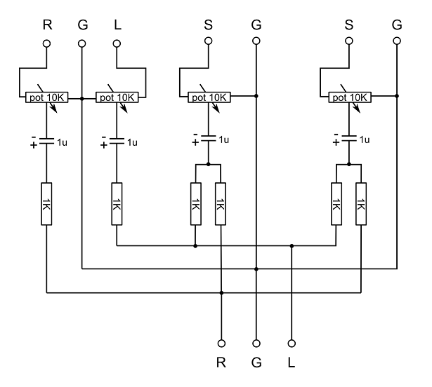 |
||||
| Warpspeed Guru Joined: 09/08/2007 Location: AustraliaPosts: 4406 |
Yes, that should work fine. Any number of mono or stereo inputs could be added, its just more of the same. Cheers, �Tony. |
||||
| Cyber Senior Member Joined: 13/01/2019 Location: UkrainePosts: 161 |
Thank you, Warpspeed! |
||||
| Pete Locke Senior Member Joined: 26/06/2013 Location: New ZealandPosts: 184 |
Yes....but no. The issue with the circuit is that you will have left and right mixing through the 1K resistors on the two mono channels. It will work, but the stereo separation will suffer. You need to have an active mono splitter to keep the stereo effect as good as it can be. Cheers Pete'. |
||||
| Warpspeed Guru Joined: 09/08/2007 Location: AustraliaPosts: 4406 |
What you say is quite true Pete, but he just wants something very simple for gaming. Cheers, �Tony. |
||||
| Cyber Senior Member Joined: 13/01/2019 Location: UkrainePosts: 161 |
What do you mean by "suffer"? I also don't unerstand one comment under the original article: Should I be concerned about this? Actually if the circuit is more or less fine, I will build it and see how it works. I'm fine if it would not give ideal mixing. I'll be using it for casual home mixing, retro gaming to be exact. And I don't have an ear for music. What I'm really afraid of is to not fry anything. |
||||
| Cyber Senior Member Joined: 13/01/2019 Location: UkrainePosts: 161 |
One more thing. As I said, I plan to mix PC speaker motherboard output with soundcard audio output. Normaly PC speaker output level is enough to drive a speaker. But soundcard output level can drive some simple headphones only. So I assume sound levels are very different. Do I have a chance to run into problem colliding such different levels? |
||||
| Warpspeed Guru Joined: 09/08/2007 Location: AustraliaPosts: 4406 |
Stereo is supposed to be two entirely different and separate channels. So in theory you should be able to have a full symphony orchestra going full blast on one channel, and have complete total dead silence on the other channel. Feeding a mono signal into both channels using just resistors will work fine, both channels will then produce the same mono signal. What Pete is saying is that one stereo channel can bleed slightly back into the other through the same mixing resistors, so instead of having dead silence on one channel, a loud signal on one channel can feed a little bit of signal back into the other channel. So it slightly degrades the full stereo effect. If you are interested in top end very high quality stereo reproduction, that is a disadvantage. For sound effects for gaming, I doubt that you would even notice the slight difference. I suggest build the circuit as you originally intended, and see how it goes. If you strike any problems we can help you solve them. Cheers, �Tony. |
||||
| Cyber Senior Member Joined: 13/01/2019 Location: UkrainePosts: 161 |
Now I get it. Yes, slightly should not be a big deal for me. Thank you! |
||||
| Cyber Senior Member Joined: 13/01/2019 Location: UkrainePosts: 161 |
Please explain me one thing: for what reason pots are connected to ground? To my understanding pots here are used to adjust input level on each channel, so I would put a pot on every channel wire (like resistor and capacitor). But would I want to ground the third pot pin? |
||||
| Cyber Senior Member Joined: 13/01/2019 Location: UkrainePosts: 161 |
I thought I'll better illustrate what I mean. In my circuits when I needed to adjust volume I did it like this. Used two pot's pins, and left third one unused. 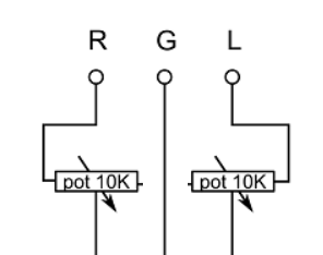 Or like this. Same as previous, but shortened unused pin to middle pin, since it's not used. 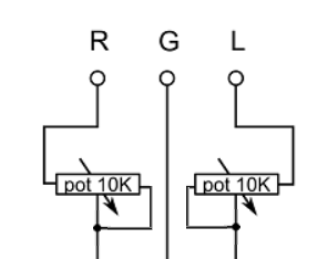 And both these approches worked fine for me. So I'm confused to see the third pin connected to ground. |
||||
| Warpspeed Guru Joined: 09/08/2007 Location: AustraliaPosts: 4406 |
That should work, but it has the disadvantage that you can only turn down the volume so far. If its still too loud on one input, there is not much you can do. By returning the potentiometers to ground, you can turn down the volume all the way down to zero. A much wider adjustment range. Cheers, �Tony. |
||||
| Pete Locke Senior Member Joined: 26/06/2013 Location: New ZealandPosts: 184 |
As Tony said, it will work but not as well as it would with an earth (ground) in the circuit. The original circuit you posted should work OK, with the understanding that the left and right channels (what you get in your left and right ear, especially with headphones on) will sound closer together. What I mean is that if your game has a car going from left to right on the screen, the sound will appear to be closer to it coming straight at you rather than from one side to the other. But build the original as has been suggested, and see how you like it. If it's not what you are after then we can help with suggestions/links to something a bit better. The other thing to bear in mind, is as it's a passive mixer, when you alter one of the volume controls, it will have an effect on the other two channels. It may or maynot be noticeable depending on the adjustment. But build it and see how you like it. Cheers Pete'. Edited 2021-03-21 18:59 by Pete Locke |
||||
| Cyber Senior Member Joined: 13/01/2019 Location: UkrainePosts: 161 |
Guys, you're great! Can you also please explain me what task capacitors do in this circuit? Edited 2021-03-21 23:59 by Cyber |
||||
| Warpspeed Guru Joined: 09/08/2007 Location: AustraliaPosts: 4406 |
The capacitors remove any slight residual dc voltage on the audio signal. Probably not necessary, but its good design practice to have them there. As Pete says, first try the circuit as presented, it will very likely work pretty well and meet all your expectations. Cheers, �Tony. |
||||
| Cyber Senior Member Joined: 13/01/2019 Location: UkrainePosts: 161 |
I built it and tested it on some mobile phones and it sounds fine to me! 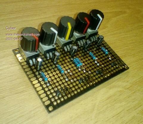 |
||||
| Warpspeed Guru Joined: 09/08/2007 Location: AustraliaPosts: 4406 |
Great stuff Cyber  Cheers, �Tony. |
||||
| Cyber Senior Member Joined: 13/01/2019 Location: UkrainePosts: 161 |
Thank you, Tony! I haven't tried it on my retro gaming PC yet, but that will come eventually, and I'll share the results. Now after I built it and it works well enough, I have a few questions about how it works. Being newbie in electronics my questions are more about why it works. Sorry for my ignorance, but I can't figure it out myself, even though I feel it is simple and basic things. 1. Why 1K resistors don't make output sound weaker? I mean resistor adds resistance to circuit and voltage should drop on resistor. For example when I need to power 3 volts LED from a 5 volts battery, I use resistor to drop voltage on LED so LED would not fry. Why output sound level (or volume) does not lower down after these 1K resistors? 2. What actually capacitors do here? I remember answer above: "capacitors remove any slight residual dc voltage on the audio signal." What I know about capacitor is that it holds charge like a small battery. Current actively flows through capacitor until it is fully charged, and after that capacitor will draw very few current only to support its full capacity. For example I use capacitors to stabilize input voltage in some electronic device. But this mixer works with sound. And sound actually is a voltage rapidly changing up and down. I would think that capacitor should ruin this process, but in reality it helps. What am I missing? 3. Potentiometers connected to ground. I asked about this above as well, and answer was: "by returning the potentiometers to ground, you can turn down the volume all the way down to zero." It works, but I still don't understand how and why. I understand that changing resistance on particular channel changes sound level on that channel. But I still don't understand how the opposite resistance thant is formed between channel output and ground helps. |
||||
| InPhase Senior Member Joined: 15/12/2020 Location: United StatesPosts: 178 |
Voltage drop is a result of current flow. If the current is small, as in an audio channel, voltage drop is small too. AC passes through the capacitor as if it isn't even there. A smoothing capacitor in a power supply only sees one polarity and so acts like a battery when the input voltage dips. In your case, the capacitor is rapidly charging and discharging every cycle, so the polarity of the output is opposite of the input. The signal passes through but DC is blocked. The potentiometer is a voltage divider formed between input and ground. By moving the output up or down, you change the voltage on the output. When it is turned all the way down, the output is connected to ground, and thus is silent. |
||||
| Cyber Senior Member Joined: 13/01/2019 Location: UkrainePosts: 161 |
Thank you very much, InPhase! I have much to learn. I'm software developer, and programming is actually not an easy thing, but I mastered it to a pretty high level. But electronics... Damn, it is so twisted and colplicated compared to programming... %) . Edited 2021-04-09 01:01 by Cyber |
||||
| Page 1 of 2 |
|||||
| The Back Shed's forum code is written, and hosted, in Australia. | © JAQ Software 2026 |
