Notice. New forum software under development. It's going to miss a few functions and look a bit ugly for a while, but I'm working on it full time now as the old forum was too unstable. Couple days, all good. If you notice any issues, please contact me.
InPhase Senior Member Joined: 15/12/2020 Location: United StatesPosts: 178
Posted: 01:27am 08 Apr 2021
Copy link to clipboard
Print this post
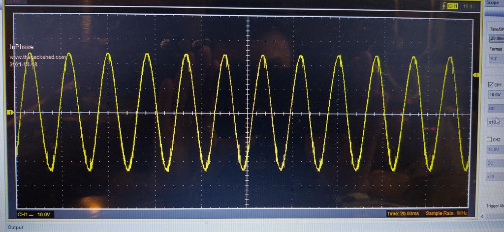
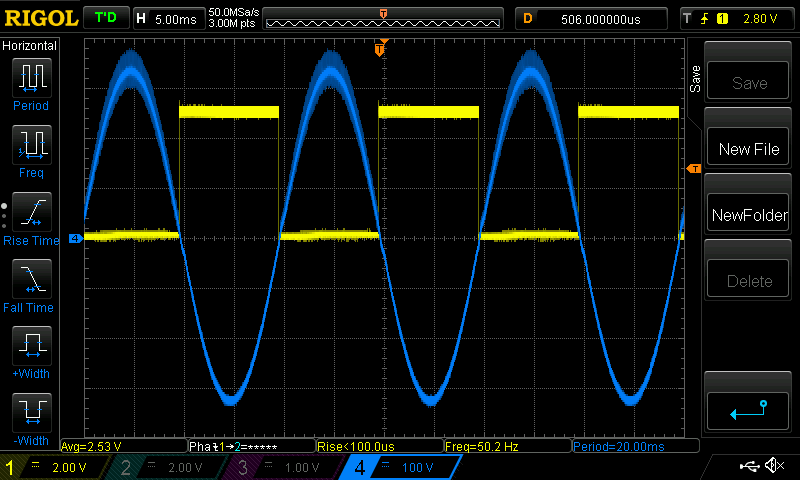
So I've managed to cobble together a working inverter based around Poida's Nanoverter. Instead of using the IRF21844 chips to directly drive the FET bridge I used TLP350 opto drivers and isolated gate drive supplies. I have tested it up to 1000 watts so far. It works well and starts a 1/2 HP pump with no problem. However, I notice some irregularities in the sine wave when zoomed in to less than 20 ms. RC snubbers don't alleviate it at all. I did notice a very slight change when I coupled the isolated supplies to power ground through some 100 nF capacitors, but not of any significance. I am powering it for testing on a big 24 V power supply, but the output of that is really clean, so I'm not sure if that could be a source of trouble. Also, the choke on the transformer primary is just 4 turns on an old transformer core with no air gap. Could that be somewhere to look?
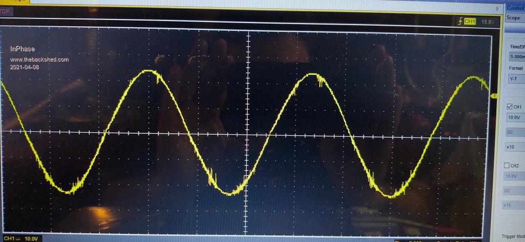
I've attached pics of the wave at 5 and 20 ms. Do the expert eyes here see this as a real problem?
poida Guru Joined: 02/02/2017 Location: AustraliaPosts: 1480
Posted: 09:39am 08 Apr 2021
Copy link to clipboard
Print this post
not really.
there is a lot of noise in these things.
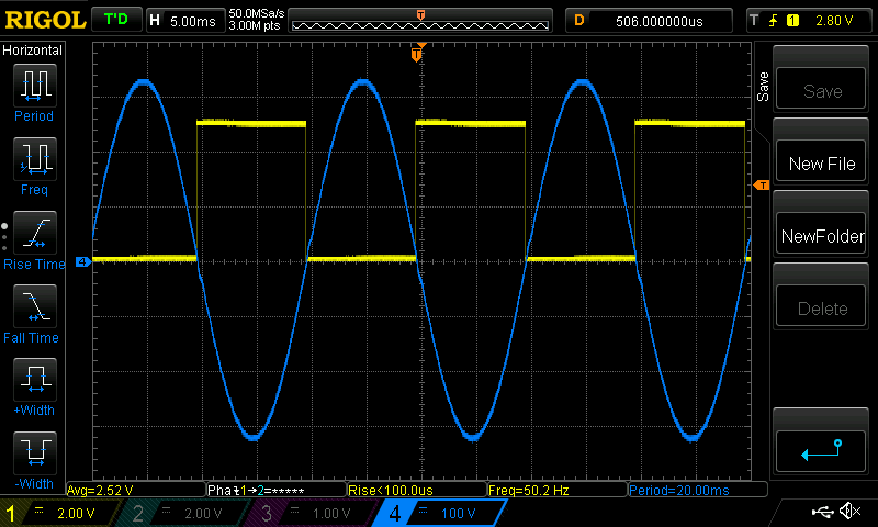
Usually I use the DSO function called "high resolution" (for the Rigol DS1054Z) This averages a number of samples to give the value to be plotted at a particular point on the display.
I think this function is probably available in your and other DSOs
This is noise. There are large and strong sources of noise with an inverter.
Why do I regard the averaging of samples over a short period of time (vis a vis "high Res" mode) to be useful or meaningful?
The DSO input stage is very good and can record fast changes in input signal. When you add the noisy environment to the signal, we will have to see a noisy signal.
I always show "high res" versions of the signal here on the forum.
The noise sources include the primary winding, the cables leading to the primary and the inductor. At 1kW and 50V that is 40A or more switching at 20 kHz with 500nS rise times or faster. This means large amounts of high frequency EMI.wronger than a phone book full of wrong phone numbers
Haxby Guru Joined: 07/07/2008 Location: AustraliaPosts: 426
Posted: 10:11am 08 Apr 2021
Copy link to clipboard
Print this post
Is EMI made worse with switching high current or is it more based on voltage rise in a short time?
InPhase Senior Member Joined: 15/12/2020 Location: United StatesPosts: 178
Posted: 10:56am 08 Apr 2021
Copy link to clipboard
Print this post
Thanks Peter! My concern comes from the fact that this noise seems to always occur in the same place on the waveform. There's a little wiggle on the down slope of the positive half and a little wiggle on the up slope of the negative half. It's very regular. I'm going to stop chasing this ghost and steam ahead.
poida Guru Joined: 02/02/2017 Location: AustraliaPosts: 1480
Posted: 11:53am 08 Apr 2021
Copy link to clipboard
Print this post
my understanding is we are putting fast changes in current through a wire. This induces strong magnetic fields.
Certainly when we increase the operating voltage of these things we also increase the current change rates sometimes.wronger than a phone book full of wrong phone numbers
renewableMark Guru Joined: 09/12/2017 Location: AustraliaPosts: 1679
Posted: 10:14pm 08 Apr 2021
Copy link to clipboard
Print this post
I'm sure Peter is correct, but that choke sounds inadequate to me, it might not be an issue at those power levels but it most likely will be if you drive it much harder.
Also when testing without caps on the power board the wave can look crap, once fitted it's cleaned up a lot. So what caps do you have on the power board?
I have had a lot of help from many people here, one thing I have found is every component needs to be fit for purpose or it will go bang at some point.
My problems all stopped when a good choke was made and the torroid tuned for 75hz for out 50hz mains in Aus. Warp did that for me, it was so long ago I have forgotten how it was done (and yes that exact setup is still powering my house)
Are you making a test unit to see how they operate or do you plan this machine to run your house?
An easier route would be to use Poida's nanoverter board and a Mad power board, that's a tested setup that's proven to work.
Perhaps some pics? Edited 2021-04-09 08:18 by renewableMarkCheers Caveman Mark Off grid eastern Melb
Warpspeed Guru Joined: 09/08/2007 Location: AustraliaPosts: 4406
Posted: 10:16pm 08 Apr 2021
Copy link to clipboard
Print this post
Its probably a bit of both inductive and capacitive coupling plus perhaps a noisy ground.
Digital oscilloscopes just take a bunch of samples and join the samples with solid lines on the screen. Any noise spikes can look truly awful. An analog oscilloscope will give a much truer representation of reality, where momentary noise just looks like a faint defocusing of the main trace.
I have both types of oscilloscopes here and much prefer a fast analog oscilloscope for some applications.Cheers, �Tony.
Warpspeed Guru Joined: 09/08/2007 Location: AustraliaPosts: 4406
Posted: 10:17pm 08 Apr 2021
Copy link to clipboard
Print this post
Very sound advice indeed !Cheers, �Tony.
InPhase Senior Member Joined: 15/12/2020 Location: United StatesPosts: 178
Posted: 02:43am 09 Apr 2021
Copy link to clipboard
Print this post
I feel this way too. I have read of the many ills caused by an inadequate choke.
I have 85000 uF to use but only have connected 15000 uF.
This is a test unit. I built it in chunks. It was a labor of learning. I needed to understand how high side FET switching worked, so I built a crazy PWM motor controller with a high side FET to find out what all the fuss was about. I then wanted to isolate it, so I hacked in an opto FET driver. I have learned a lot about power MOSFETS in the last few months. That's the primary reason I set out to build the contraptions I do.
If I needed an inverter for home power usage, I would absolutely just do that. I might even just buy one retail for that matter. But 79.77% of this project is simply to do it from almost-scratch. Once I test it to the 4 kW design goal, all I have learned will be translated into one or two boards. Right now, it is 8 individual protoboards screwed to plywood. I'll get some pics.
I am very grateful for the wealth of knowledge here. I have read so much of this forum now. I spend most of my time in the deep back pages.
InPhase Senior Member Joined: 15/12/2020 Location: United StatesPosts: 178
Posted: 04:13am 09 Apr 2021
Copy link to clipboard
Print this post
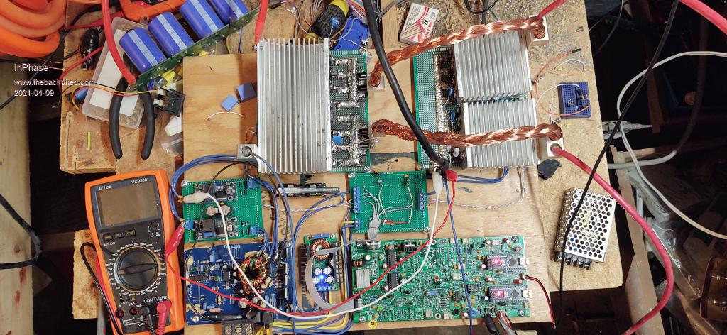
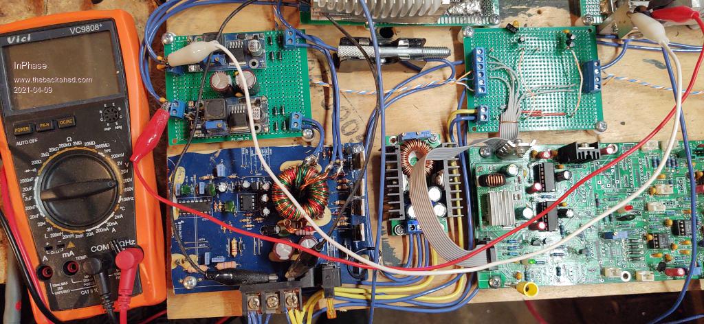
Here's some pics of the bodgery. I guess it isn't hard to see how some noise might creep into the works.
In the first pic you can see the two FET boards with the heat sinks. Both high sides on the left, and both low sides on the right. Going clockwise from there is Poida's Nanoverter board. I have two Nanos installed, but only the inverter function is being utilized. To the left of that is the low side gate power supply. Then is my DIY isolated high side gate supply. It used to be the power supply on an old car audio amp. It has a TL494 driven push pull transformer with two output windings. Each of those windings goes to the next board to be rectified and fed into the two buck converters which now are isolated high side power supplies.
Under the heat sinks are TLP350 opto gate drivers which in turn feed BJT totem poles for each quarter bridge.
I know it is a sloppy mess. But I've had one hell of a fun time doing it. When I complete high power testing, I will boil it all together into a couple of ordered PCBs in a box.
poida Guru Joined: 02/02/2017 Location: AustraliaPosts: 1480
Posted: 06:29am 09 Apr 2021
Copy link to clipboard
Print this post
I think I know where the rough looking waveform is coming from. Long wires carrying large currents that are undergoing fast rates of change.
Mark is also on the right track.
Once you give it some decent capacitance on the DC input you will see it improve a bit. Whoops, I see you have 15,000uf. That is enough for good testing setup.
You can try different LC filters and see what gives a nice looking waveform
I found there was a wide range of inductance and cap pairing that worked fine on the bench with low loads. It was informative to try a few combos and see the waveform and DC input current on idle.
But once you want to use it under large loads you need to have - about 47uH inductor that does not saturate at about 2x DC input current for maximum load - a cap on the AC output such that the toroid primary winding resonates at about 50 to 75Hz. My inverter resonates at about 35Hz and is marginally too low.
This LC filter is needed to remove all of the 20kHz switching energy. Since it is a squarewave, there will be harmonics of not insignificant energy too. 20kHz, 1/3 power at 60kHz, 1/5 power at 100kH, etc.
These are noisy beasties. Edited 2021-04-09 16:32 by poidawronger than a phone book full of wrong phone numbers
poida Guru Joined: 02/02/2017 Location: AustraliaPosts: 1480
Posted: 06:58am 09 Apr 2021
Copy link to clipboard
Print this post
probing the AC output for me requires some care since it is 240V AC RMS Peak voltages can be 340V.
I do not just connect a probe's ground clip to one wire of the AC output and the probe tip to the other. I use an isolated differential probe for this. It has a decent bandwidth, of the order of 25MHz The two leads for the differential input are unshielded DMM clip leads so they will pick up lots of other signals.
With the boilerplate out of the way, let's see what the test inverter is today:
Under 200W load. (57V input, 235V AC out)
Notice the noise on 1/2 the wave? I have no idea where it comes from. Maybe a marginal totem pole drive. I have blown this board up more than 4 times now. This is using the acquisition mode "normal"
Now when I use "high res" acquisition mode the noise is averaged out.
I know there is noise and I know there are problems with my test inverter. But sometimes that is not important in the discussion I am having at a particular time. So I smooth the traces so they look nicer.
Can you tell me a bit how you probe the AC output and what settings the DSO of yours has in effect for the captures?wronger than a phone book full of wrong phone numbers
InPhase Senior Member Joined: 15/12/2020 Location: United StatesPosts: 178
Posted: 11:08am 09 Apr 2021
Copy link to clipboard
Print this post
My scope is a USB unit that plugs into my laptop. It can measure up to 20 MHz. As far as I can find in the settings, there is no averaging function.
At first, I just used a resistor voltage divider to bring the AC output down to a level safe for the scope. But now I look at the signal from the 12 V feedback transformer. In the above pics you can see the probes clipped to the diode leads at the Nano board feedback input.
nickskethisniks Guru Joined: 17/10/2017 Location: BelgiumPosts: 481
Posted: 11:58am 09 Apr 2021
Copy link to clipboard
Print this post
Hi, nice testing setup.
For a next time it is better to build 2 Half bridges, instead of what you have now. The reason for that is that now your capacitors are to far away. You won't have a stable DC bus at the mosfets, at the capacitors you might have a stable voltage but, that's not the case at your MOSFETs, the higher the current, the higher the spikes at your MOSFETs, and the closer to MOSFET failures.
Try to add some decent low esr/ESL +/-4,7uF capacitor between the low side MOSFET source and high side MOSFET drain, with the shortest possible path to surpress the transients. This might help. I see you already added snubbers. Edited 2021-04-09 22:01 by nickskethisniks
wiseguy Guru Joined: 21/06/2018 Location: AustraliaPosts: 1297
Posted: 03:09pm 09 Apr 2021
Copy link to clipboard
Print this post
I like that fuse in the centre of the top picture, should be good for at least 300A lol. I use an old brass pot shaft 1/4" (6.3mm) dia for the same thing at times. When everything becomes a smoking vaporised ruin the fuse will be the only thing left intact.
The isolated supply is impressive but a little overkill, I estimate you only need ~ 100mA max per high side drive. What was the pcb from - a car stereo or similar?
Congrats on making it all work, agree needs more choke work & capacitors as per Nicks comments. I am surprised the cro images are as good as they are given the layout. Edited 2021-04-10 01:17 by wiseguyIf at first you dont succeed, I suggest you avoid sky diving.... Cheers Mike
InPhase Senior Member Joined: 15/12/2020 Location: United StatesPosts: 178
Posted: 04:35pm 09 Apr 2021
Copy link to clipboard
Print this post
I was wondering if anyone would notice! We might be related. Dad went all over the world in the army.
Yes, I agree. It's a bit much. I had one isolated supply, but not two. Being the cheap bastard I am, and not knowing if any of it would work at all, I rigged that up. It is a cheap-o subwoofer amp board. I mapped it out and chopped the amplifier section off. Now that I have proven the whole inverter concept to myself, I'm going to streamline everything into one or two PCBs. I want to get rid of the ribbon cable completely and get the driver board as close to the FETs as possible. I MIGHT even buy some nice isolated supplies. MIGHT. One of the goals of this project was to make a device that could be repaired with salvaged hardware... So I am kinda partial to my high side supply hodge...
Thanks! I am still not up to speed on the tuning of my toroid. I've been reading about it. Right now, the capacitor on the output is 1.5 uF. The next highest size I have of a high voltage film capacitor is 15 uF, and it is way too big. The wave is really nasty with that one fitted. I need to get an assortment to have on hand.
I'm going to do some choke tweaking when I get home today.