| |
Page 1 of 2   |
| Author |
Message |
hary
Regular Member

Joined: 15/04/2019
Location: FrancePosts: 89 |
| Posted: 07:15pm 09 Apr 2021 |
 Copy link to clipboard Copy link to clipboard |
 Print this post |
|
Hi all.
Well, all is in the title.
I've 3 of those in 12VDC/220AC
One 1250W, one 3000W, and another 6000W.
I don't really need them as I'm now on 24V, but repairing the 1250W or the 3000W would be nice to put on the van.
It would mainly be for learning. |
| |
BenandAmber
Guru

Joined: 16/02/2019
Location: United StatesPosts: 961 |
| Posted: 11:02pm 12 Apr 2021 |
Copy link to clipboard |
Print this post |
|
Since no one else has commented
I guess I a grasshopper among giants will
If the price of parts is free or cheap why not get a little practice and fix them
Keep in mind i am someone that stripped out a 5000 watt Ames high frequency inverter to use the case
The aims inverter worked perfectly
I had ran small air conditioners and other loads with it
I needed the case for a $30 four mosfet in total low frequency china EGoo2 board
That was a few years back now so you may ask would you do it all over again
I would say HELL YES!!! It was one of the best things I ever done
That little inverter didn't only keep my mind off heath problems
It brought wife and I closer gave my bearly functioning at the time brain exercise and showed me I was wrong there are still humble generous caring all around amazing people left in this world
Sure tinker with your broken high frequency inverters
Keep in mind it it is a gate way inverter that leads to the stronger more powerful low frequency inverter
One day your tinkering around experimenting with a high frequency the next you spend your last dollar on tranny tape before you know it your in back shed up all night with wire in your hand telling yourself just one more turn and I'll quit
Wife will find you early the next morning talking to yourself half frozen to death Dazed and Confused still saying to yourself just one more turn and I'll quit
Seriously though if you get stuck humbly and respectfully post about it on here (include pics and lots of details)
Be patient and some one will have pitty and give you a word of wisdom after many comments telling you they don't
like and why high frequent inverters suck
From my experience they will require you to be trying hard to figure things out yourself and not just wanting the answer over and over
I took this as a good thing it made me SLOWLY SO SLOWLY start to understand what I once thought couldn't be that hard
It is a hobby that would take more than a few lifetimes to fully understand everything always something new to learn alot of these guys on here makes it look easy with there art pieces they call inverters
They get you drooling with a pic here and there but just like those (cocktail waitresses) at them places you shouldn't go they always leave you wanting more
You have been warned ahead of time this kind of tinkering can turn into a all out addiction quicker than crack cocaine lol
Unlike crack it will likely save you money with the continuous gain of understanding on all things electronic you will find yourself fixing instead of trashing
If your lucky a few life lesson that are almost extinct nowadays
my come your way also so on here are not spring chickens and have some of that knowing that only comes with many years lived
This site has the largest group of brilliant but humble generous doers not just talkers I have ever came across
Some are highly educated Geniuses others are self-taught geniuses some not so much or even a little slow but brain won't stop intill they finger it out like myself
(Me) poor and like it that way middle class and very well to do
All come together and sure thoughts plans and ideas generously without any thoughts of getting something in return
most not myself take giving advice very seriously Do you want a quick advice or well thought through advice
In my life these kind of people was like a hillbilly that doesn't love shot guns Jesus biscuits and gravy
Also them stars by a person's name along with names like newbe represents how much you post not your skill level
The Administrator is very cool unless you cause a uproar by speaking truth strongly or opinions on subjects that have nothing to do with this site that anyone with good common sense wouldn't speak of anyway and it has to be pretty bad like very strong religious opinions the shape of very big things or strong opinions on politics only if it's offensive to others
If this this happens tust me when I say it will be the last time
Well my friend that was the just of things around here
If you read this book of a post and made it this far
You definitely need a hobby electronics is a very good always something new one
Hope to see you posting you progress WITH PICS
Have a blessed day my friend
be warned i am good parrot but Dumber than a box of rocks |
| |
Haxby

Guru
Joined: 07/07/2008
Location: AustraliaPosts: 426 |
| Posted: 11:28pm 12 Apr 2021 |
Copy link to clipboard |
Print this post |
|
Harry, welcome!
You answered your own question in your last sentence.
"It would be mainly for learning".
Who would object to that?
This group mostly discusses LF designs for whole-house off grid use. We concentrate on low idle power, and (very) high surge rating designs for starting fridges, water pumps, etc.
The fact that you have 3 faulty HF inverters is a clue that they are not very reliable. They are fine for small loads with low startup current, but look at the surge currents Poida measured on an air compressor starting up. A HF inverter would shrivel up and poop itself just at the sight of that load. It's the difference between a motorbike and an 18 wheeler Mack truck. One of them can cruise 24/7 and click over a million miles with ease. The other needs constant attention.
Ask specific questions about your inverters and we will be sure to help  |
| |
Murphy's friend

Guru
Joined: 04/10/2019
Location: AustraliaPosts: 678 |
| Posted: 07:25am 13 Apr 2021 |
Copy link to clipboard |
Print this post |
|
Hary, all of the advice given here is free. You do well to research posters that replied to your question and judge credibility from there.
B&A turned up here back in early 2019, made a thorough nuisance of himself by posting a lot of attention seeking nonsense back then which has seen little improvemend since.
There is a *lot* of truth in his byline. |
| |
Revlac

Guru
Joined: 31/12/2016
Location: AustraliaPosts: 1282 |
| Posted: 09:10am 13 Apr 2021 |
Copy link to clipboard |
Print this post |
|
I would agree its worth trying them, see whats wrong and if repairable (at little expense) and might learn a few thing's along the way, have done this myself.
I have no idea what powerjack use inside those inverters, so some photos might be somewhat educational.
Anything less than 48v in a HF inverter I have kept clear of, personal preference for a 48v system.
Some Hf inverters have improved there designs over the years and run a full H-Bridge totem driver design And are (mostly) not difficult to repair, learnt to repair one while building one of the LF Mad inverter's here.
Some HF inverters can start and run medium size power tools and Some induction motors but not all, they might get there one day but not there yet.
The HF inverter Typically have have a surge rating only twice as much as its continuous rating, The LF type has much more, plenty to read up on around here.
I run both HF and LF inverters and Now mostly LF inverters to handle all the tough stuff, large motors and power tools etc, no problems yet.
Its always fun learning whats inside all these electronic things, and how they work OR NOT WORK. 
Edited 2021-04-13 19:12 by Revlac
Cheers Aaron
Off The Grid |
| |
BenandAmber
Guru
Joined: 16/02/2019
Location: United StatesPosts: 961 |
| Posted: 09:29pm 16 Apr 2021 |
Copy link to clipboard |
Print this post |
|
This is a really fun hobby if you have the time for it
Anyone can join this hobby on any skill level
Check out poida he has made a inverter plus a charge controller
he shares the files to get boards made cheap
Warpspeed has one also mac has a few
Last few boards I got made thew pcbway the shipping was more than the cost of the boards
Don't be down hearted over something negative you know it takes all kinds
people bend over over backwards on here to help educate and give freely
I get lots of joy from helping also even though I am no pro!!
Lots of posts do add to the difficulty in finding information needed but that is the internet lol
If a person can get good at searching through this form most questions have been answered many times
Our pros on here have the patience of Job
I am not on here very often anymore but will help in any way I can
Have a blessed day
Edited 2021-04-17 13:05 by BenandAmber
be warned i am good parrot but Dumber than a box of rocks |
| |
hary
Regular Member
Joined: 15/04/2019
Location: FrancePosts: 89 |
| Posted: 07:18am 17 Apr 2021 |
Copy link to clipboard |
Print this post |
|
Hi all.
I first had a look to this one, below :
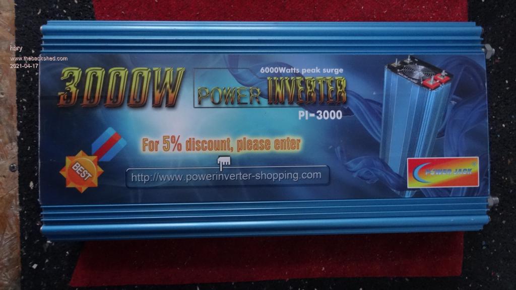
It was beeping, so I took it out of the case and checked for different things about burned fuses or MOSFETs, voltage on the first and second stage, etc.
It was like turning on and off rapidly.There was nothing burned, no fuses, no MOSFETs.
There were 6 small transformers fed by 2 fuses for each, then the output of that 6 transformer were in series.
So I took the fuses off and what I noticed is that with only 1 or 2 of the primary stage transformers, it would not beep and turn itself in security state as the output voltage on the first stage was lower (less than 180VDC).
With the 6 transformer on, the output voltage was around 250VDC, but was difficult to measure as the inverter was rapidly turning on/off.
I could light up an incandescent 60W light bulb from that 160-180VDC.
So I thought there was something wrong about the first stage feedback loop, so the inverter first was to high in voltage and it would put itself in some kind of security state (on/off behavior).
I started to check around that direction on a control board and first think I've noticed was some lack of tin on some welding.
I wanted to trace that feedback track before doing anything, but fortunately (or not), putting back the control board in place for some deeper expertise, the inverter seemed to start well without beeping.
As I have been touching lot of connection, I was pretty sure there was a bad solder joint somewhere.
I spent some time redoing most of the solder I could, then put everything back, and the inverter seem to give 230VAC at its output.
But for sure I was a little stupid.
As I was so excited, i didn't take much time to check different voltages at different stages in the inverter, or even check the MOSFETs' driver signal with my brand new oscilloscope before closing the box. |
| |
BenandAmber
Guru
Joined: 16/02/2019
Location: United StatesPosts: 961 |
| Posted: 10:59am 19 Apr 2021 |
Copy link to clipboard |
Print this post |
|
That's great news
Did you get a chance to read a little on poidas last post
He said soon he will be sharing his new low frequency board
Warpspeed has a awesome inverter design also
Have you thought about building a low frequency inverter yet lol
It is very rewarding and lots of fun
I took the short cut on alot of the inverters I have built by buying a premade mainboard
It makes for a quick and easy build especially for non pros like myself
I run over 2000 watts all the time on my little 4 mosfet in total China board
It was 30 around bucks
I may have a few parts laying around if you deside to go this of any other route
Have a blessed day
be warned i am good parrot but Dumber than a box of rocks |
| |
hary
Regular Member
Joined: 15/04/2019
Location: FrancePosts: 89 |
| Posted: 06:55pm 19 Apr 2021 |
Copy link to clipboard |
Print this post |
|
Hi all.
An horrible thing happened to me !
This :
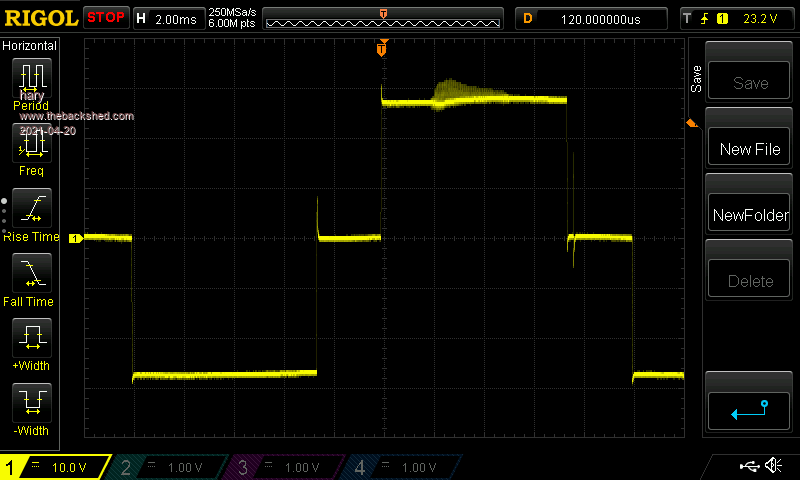
I was thinking I had fixed a true sine wave inverter ! I'm very disappointed.
Edited 2021-04-20 04:56 by hary |
| |
hary
Regular Member
Joined: 15/04/2019
Location: FrancePosts: 89 |
| Posted: 07:01pm 19 Apr 2021 |
Copy link to clipboard |
Print this post |
|
BenandAmber, I did think about it once. I was even thinking it would be the only way to have something reliable.
In fact, because of you all, I did so, a while ago, but I'm not able to find back the thread I've been posting here 1 or 2 years ago.
It was a very small one because of the transformer I had at hand.
I was in a hurry for the inverter at that time, and building one would have taken a lot of time, and my main problem was the transformer. I had no core for it and no idea where to source one.
Finally, I found a Chinese 6kVA LF inverter with a toroid (32W idle) for 600-700Euros shipping included.
I thought, even if the rest of the inverter fail, I'll still have a toroidal transformer to rebuilt it TheBackShed style.
The small one I made works, but it couldn't start inductive loads, not even the small 100W fridge.
But now I have all these broken inverter, A power bench PSU, an oscillo, I thought it would be interesting to dig in a little more.
I even thought of recycling one of these inverter to make one with variable/controlled frequency to be used as a VFD to softstart and run the fridge.
As I told you just before, I've been disappointed when I realized the inverter I "fixed" wasn't a true sine.
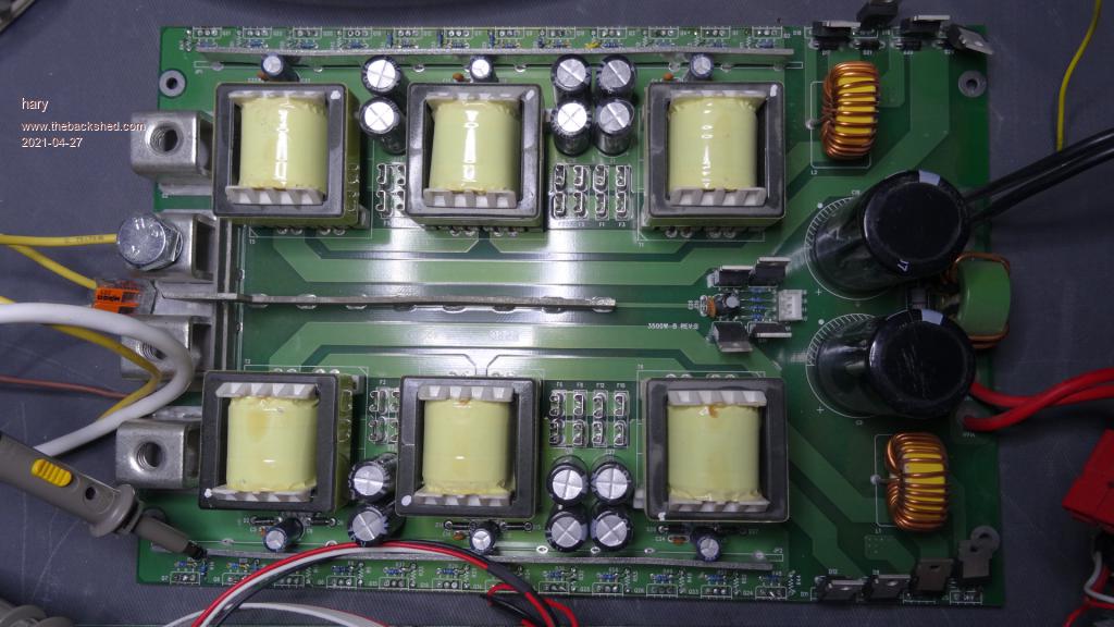
Another broken one I have is the same as the one in this page :
https://ludens.cl/Electron/chinverter/chinverter.html
And As you can see, it seems to have a lot of trouble. Thus, I'm not sure it is worth it to spend time on it despite I already bought some new IGBT for it.
I still have my small homemade LF inverter, but I'm not sure I could use it as a VFD as the LF transformer is for 50Hz.
Edited 2021-04-20 05:03 by hary |
| |
BenandAmber
Guru
Joined: 16/02/2019
Location: United StatesPosts: 961 |
| Posted: 07:58pm 19 Apr 2021 |
Copy link to clipboard |
Print this post |
|
It would likely cost to much for me to send you a tranny
You can change your inverter to pure sine wave
There is a few videos on YouTube showing how to do it and it looks fun!!
They use a egs002 on the output stage
That's horrible you can't find a big tranny for your diy inverter
When I get time I will be changing the fets on my little one to from 200amp hy4008 to 360 amp hy5608
Mine will start anything even air conditioner and air compressors
I did lots of modifications to mine already including really big caps
I am thinking after new mosfets it will do over 3000 watts continuous after that
I would like to see you get a big tranny if I can help in anyway let me know
There may be some one on here that has a extra one that lives closer to ya
Wouldn't that be great
Do you know ball park guess in what shipping is to you from usa
be warned i am good parrot but Dumber than a box of rocks |
| |
hary
Regular Member
Joined: 15/04/2019
Location: FrancePosts: 89 |
| Posted: 05:29pm 26 Apr 2021 |
Copy link to clipboard |
Print this post |
|
Hi.
I've opened the DC12V/AC230V 3500W with charger/UPS function.
I noticed most of the Mosfets were dead plus the 10R resistors from the driver to Gate. Everything else on the board seems to be ok.
I've taken all the dead components off to check that all the rest was ok.
I'd now like your point of view of my observation below about the driver's signal.
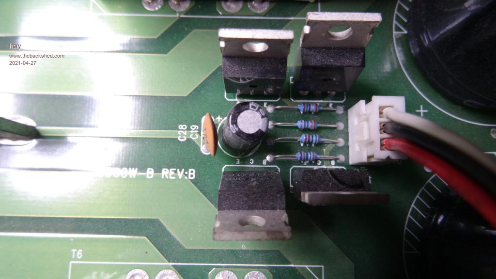
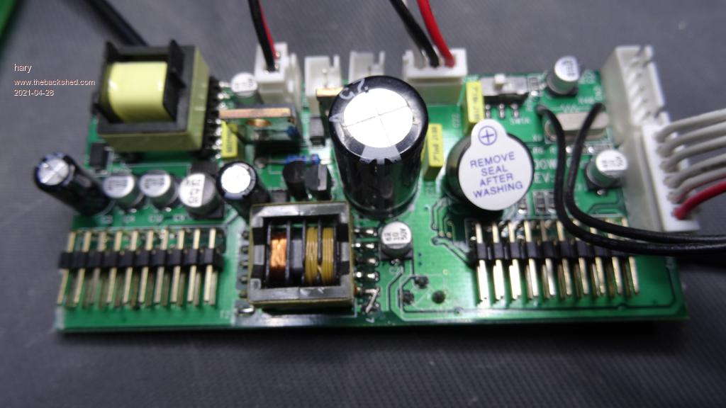
The inverter is made of 2 boards :
The 1st one hold all the control of the second stage of that HF inverter plus the charger/UPS functions and the second stage of the inverter.
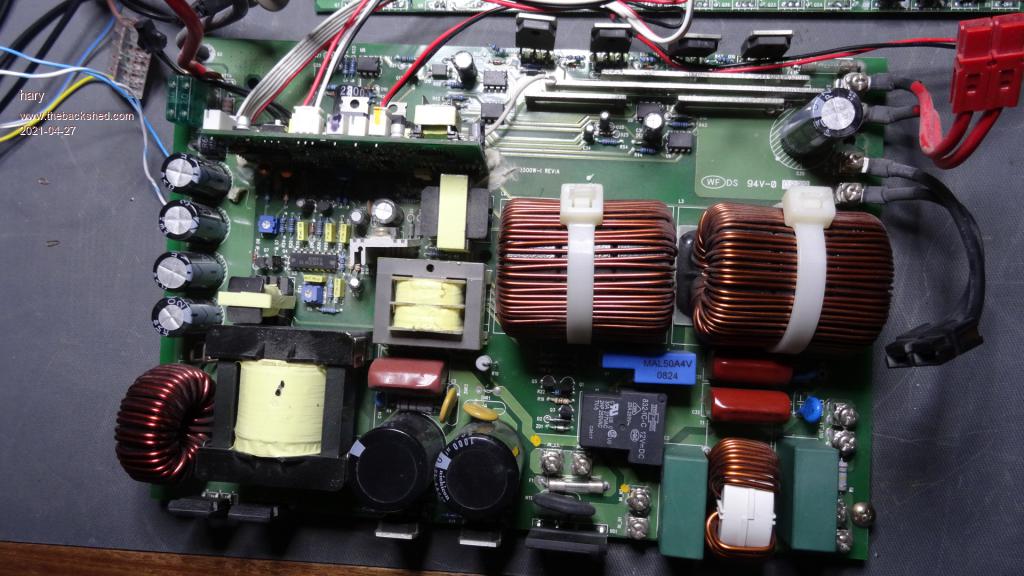
The 2nd board only hold the DC12V/DC200+ boost converter and the 2 Push-Pull Mosfets drivers made of 2 pairs of TIP41C and TP42C.
Here is a closer look at the driver :
Here is the sigal I get from the control board or after the Push-Pull driver.
As you can see the signal doesn't seem to be perfect as it shows some down spike close to 7.5V.
I wonder whether I can trust that driver's signal or not:
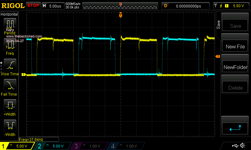
I would like your advices before putting a all bunch (24) of new IRF3205. |
| |
nickskethisniks
Guru
Joined: 17/10/2017
Location: BelgiumPosts: 481 |
| Posted: 05:52pm 26 Apr 2021 |
Copy link to clipboard |
Print this post |
|
It looks like there is a problem with the voltage supplied to your gate driver circuit. There is about the same period between the spikes, so I would look in to that, are these without MOSFETs connected? |
| |
hary
Regular Member
Joined: 15/04/2019
Location: FrancePosts: 89 |
| Posted: 06:49pm 26 Apr 2021 |
Copy link to clipboard |
Print this post |
|
Yes sir.
Without the mosfets and the same signal appears before the Push-Pull or after.
I mean, same signal without the push-pull connected.
This inverter embed a TL494, a KA7500 and a SG3524.
So the signal with the spikes are out of one of these 3 chips.
I wonder why that inverter need 3 of those chip that have the same purpose :
Maybe 1 for the 1st stage boost converter, 1 for the charge function, and the 3rd for ???? |
| |
Pete Locke
Senior Member

Joined: 26/06/2013
Location: New ZealandPosts: 184 |
| Posted: 09:17am 27 Apr 2021 |
Copy link to clipboard |
Print this post |
|
It may or may not work, but in the golden age of T.V repairs, if we had a set that would blow expensive (in those days) line output transistors, we would substitute a 1N4001 diode as the base emitter junction to allow the drive circuit run and load the collector supply with a lamp. This would allow us to see the drive wave form, and sort the fault from further back.
Just wondering if an equivalent gate/source capacitor for the FET could be used for drive issue tracing.
Cheers
Pete'. |
| |
hary
Regular Member
Joined: 15/04/2019
Location: FrancePosts: 89 |
| Posted: 07:55pm 27 Apr 2021 |
Copy link to clipboard |
Print this post |
|
@Pete Locke. I'm not sure to understand 100%, but I don't think I need such a trick as I can still run the driver without the rest of the circuit.
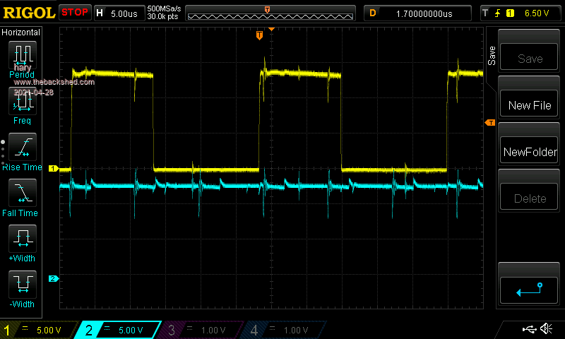
Here again, without any load on its output, in yellow the signal from pin14/outputB of the SG3525 where the Push-pull is triggered from, and in blue the VCC. As you can see, the spikes are also present on the power line and seem to be synchronised
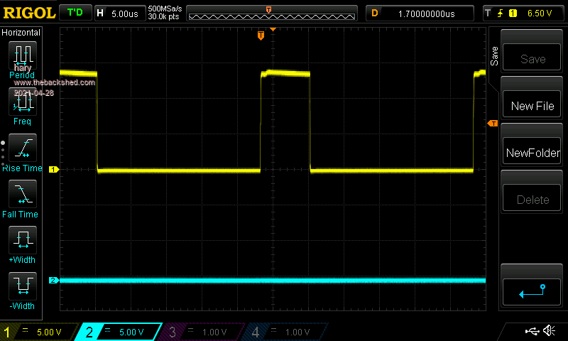
Here, the signal of a spare SG3525 I powered up on the bench. The signal just looks perfect. So I really don't think I can just replace the lot of IRF3205 and power it up.I first need to get a nice commande from the SG3525.
I would appreciate some specialist feedback |
| |
nickskethisniks
Guru
Joined: 17/10/2017
Location: BelgiumPosts: 481 |
| Posted: 08:05pm 27 Apr 2021 |
Copy link to clipboard |
Print this post |
|
Have you probed that 12V gatedriver power supply? You can use some kind of marker pen to trace down that 12V to the place were it is created. Or probe some random low voltage (probably 16-25V)capacitors around some high HF transformers to find the circuit. It's possible they first create a stable/constant voltage from that battery input voltage.
Edit: ok, you posted some other pics while I was writing...
As I said, look in that stage where that 12V is created. Makes me wonder, probably not the cause but are the output igbt's connected, is this stage also active? Make sure there is no short between input DC and output AC.
Edited 2021-04-28 06:11 by nickskethisniks |
| |
hary
Regular Member
Joined: 15/04/2019
Location: FrancePosts: 89 |
| Posted: 08:41pm 27 Apr 2021 |
Copy link to clipboard |
Print this post |
|
That inverter is a DC12V/AC230V, so the control board seems to be supplied directly from the battery, no kind of buck converter in between.
Here is the control board :
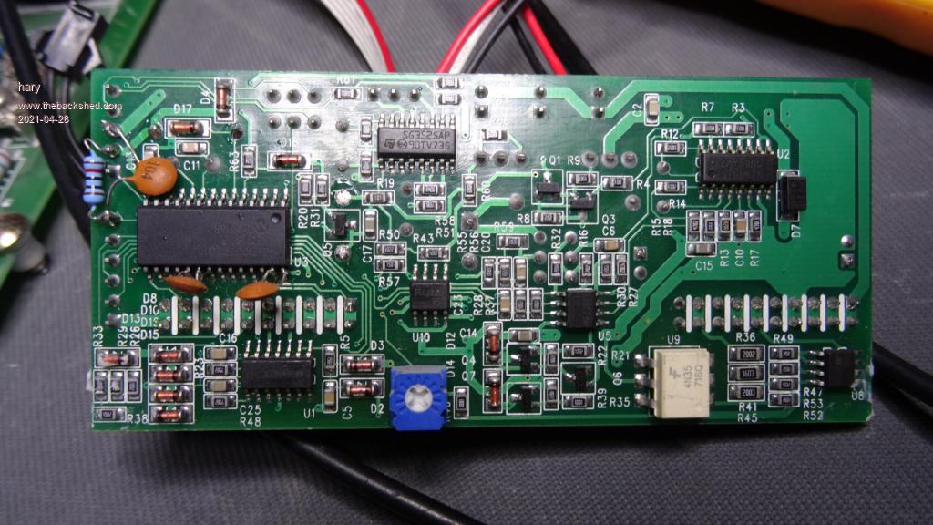
Even on that big 2200uF cap, I can see the spikes !
I've disconnected the second stage's IGBT to be sure not too make trouble, but I don't think the second stage driver would start before the control board get a 200+VDC from the 1st stage. |
| |
nickskethisniks
Guru
Joined: 17/10/2017
Location: BelgiumPosts: 481 |
| Posted: 08:26pm 28 Apr 2021 |
Copy link to clipboard |
Print this post |
|
Ok, you are sure? Are you using a battery or power supply to power the inverter? Small chance it's caused by your supply because you spikes look to be synchronised to your gatedriver signal. I'm going to sleep on it. |
| |
hary
Regular Member
Joined: 15/04/2019
Location: FrancePosts: 89 |
| Posted: 05:43am 29 Apr 2021 |
Copy link to clipboard |
Print this post |
|
Hi nickskethisniks.
It's powered with a bench SPSU (ruiden RD6018).
But on that post https://www.thebackshed.com/forum/ViewTopic.php?PID=168015#168015#167935
the 2nd picture shows the output signal of a spare SG3525 alone that I powered from the exact same bench PSU and it looks perfect !
I might try to power the control board with a shorter/bigger line to ensure no lack of power. I'll give you the feedback soon |
| |
| |
Page 1 of 2 |
