
|
|
Forum Index : Electronics : Siglent ISFE Isolated Front End module
| Page 1 of 2 |
|||||
| Author | Message | ||||
| nickskethisniks Guru Joined: 17/10/2017 Location: BelgiumPosts: 481 |
Hi, I was looking for another scope when I found this module: https://www.siglent.eu/product/1142088/siglent-isfe-isolated-front-end-module I want to look in to the switching signals in a half bridge in the near future, so measuring the 2 gates at the same time, and looking at the two D-S transitions at the same time would be my main goal. This looked to be a good option. Would this be suitable? 25khz would be the minimum frequency I like to test at, is 1Mhz bandwidth enough to see the oscillations for example? I know you can't expect the world for this price. I came across some discussion here: https://www.eevblog.com/forum/testgear/siglent-isfe-scope-front-end-isolator-any-opinions/ Edited 2021-05-15 19:53 by nickskethisniks |
||||
| Warpspeed Guru Joined: 09/08/2007 Location: AustraliaPosts: 4406 |
One Mhz bandwidth is pretty limited and I doubt if you could really see much which would be useful. I cannot see this as a bargain at the price. How about an old Tektronix A6902B ? Two input channels fully isoloated to 500v above ground, dc to 20 Mhz bandwidth, 20mmV to 500v per division displayed on your oscilloscope. These are now about twenty years old and obsolete, but they do come up quite regularly on e-bay and from secondhand equipment brokers. Prices vary a lot depending on physical condition and the probes/accessories that come with it. Here is the service manual for it: https://archive.org/details/tektronix_A6902B/page/n1/mode/2up Cheers, �Tony. |
||||
Haxby Guru Joined: 07/07/2008 Location: AustraliaPosts: 426 |
I recently had the same question here Seems like a common problem for us inverter builders. |
||||
| nickskethisniks Guru Joined: 17/10/2017 Location: BelgiumPosts: 481 |
Hi Haxby, Would the micsig dp10007 be a better choice voor gate measurements? It should have a lower noise level, 15mV instead of 40mV. Here is a comparison between the pintek dp25 and de micsiq dp10013: https://www.youtube.com/watch?v=892RcsIUAtU Because I can't find the dp-25 in EU, I'm looking at the pintek dp-65 now, should fit my needs and beyond at this moment but 369eur... https://www.eleshop.nl/pintek-dp-65-differential-probe.html For the same price I could buy 2 micsig's dp10007 or higher voltage rated... Something to sleep on. |
||||
| poida Guru Joined: 02/02/2017 Location: AustraliaPosts: 1480 |
I have both the Tek A6902B and the DP-25 The DP-25 has much less noise, is accurate and stable immediately upon power up and is very compact. The A6902B is none of the above. I could improve calibration with a couple of hours fun with internal adjustments and the service manual. Zero drift was about 3 divisions over a 30 minute warm up. One thing I noticed was how nice it is to have two channels. The DP-25 is only single channel. 2 channels means you can put both low and high side signals through identical signal paths and then have the result effected by the same delay, freq. response and gain. The much larger noise in the output of the A6902B can be dealt with nicely with the DSO "average" capture modes since we are looking at repetitive signals that can be triggered off of reliably and with good time precision. If you are thinking of getting a A6902B, there are a couple of probe options. The option with 500V probes is probably the best. These probes are quite like normal 1:10 Tek probes. They are much more compact than the 3000V type that is an option. If I was starting again, I would be happy with the A6902B only. But I would want one that has both 500V probes, looks in perfect condition and was tested for correct operation of all controls and 2 channels. The attenuation knob is a flimsy plastic linkage and could be prone to breaking. And likely an irreplaceable part. Prices range from $90 US for a one probe (3000V) and zero accessory to about $180 for both probes, manual, good condition and tests OK. It's power supply is universal and only needs the voltage selector to be correctly positioned for your mains voltage. A subtle thing with the 2 channels is that the ground clips for both channels are isolated from signal ground/supply AS WELL AS EACH OTHER. So you can put one ground clip on phase 1 of 240V 3 phase, the other clip on phase 2 and measure phase 3, all without exceeding the 500 V probe rating, and not blowing things up. But there is a fair bit of common mode interference. wronger than a phone book full of wrong phone numbers |
||||
| Warpspeed Guru Joined: 09/08/2007 Location: AustraliaPosts: 4406 |
That is all extremely helpful Peter. In spite of its massive size an "clunkiness" of the A6902B, I agree that having two matched and totally isolated channels is a big advantage, and its definitely the lowest cost way to get TWO totally isolated inputs. For what we inverter guys will mostly be using it for, ultra low dc drift and noise are not really a major concern, mainly just sufficient speed to see ringing and overshoot and measure dead times and so on, with higher amplitude digital waveforms. The Tektronx should also be repairable if it ever does take a dump. Not sure about the others, as these days schematics, service information, and spare parts are never available from anything that ever comes out of China. Multilayer surface mount boards are also just about impossible to trace out, and many of the components will have no identifiable markings on them. If you burn a resistor for example, no way possible of knowing what it was. The Tek on the other hand uses all ancient through hole readily identifiable and available parts. Cheers, �Tony. |
||||
| poida Guru Joined: 02/02/2017 Location: AustraliaPosts: 1480 |
Warp, I used AC coupling on the DSO to cure the DC drift completely Nicks, if you want to start experimenting now, and have a 4 channel DSO how about you set it up like so: All DC coupled inputs channel 1 = trigger/sync ch2 low side Gate, referenced to DC ground 5V/div ch3 high side Source, referenced to DC ground 5V/div ch4 high side Gate, referenced to DC ground 5V/div DC offset ch3 and ch 4 to fit the 50V peak in the middle of the display. It may not be possible to get enough DC offset from DSO control so use different V/div.. capture the event, maybe use average or high res. mode Then save the capture as a CSV file. (my Rigol can do this, not sure if your DSO can) Import into Excel, add an extra column, which will be (ch4 - ch3) Look at results. This approach will cancel all signal delays between high and low Gate voltages. The DSO should have fine adjustment for channel to channel delay matching. The reason I did not use built in math functions of the DSO is because they are very poor quality results. MAybe your DSO has usable math functions, i.e. display (ch4 - ch3) on screen But the Rigol's math function is not good enough. wronger than a phone book full of wrong phone numbers |
||||
| nickskethisniks Guru Joined: 17/10/2017 Location: BelgiumPosts: 481 |
Thanks for the replies, difficult choice.  Nope, I don't have a 4 ch scope, it's on my long "to buy" list, I own an owon SDS7072, nothing special. But since the pintek comes out better, I think I can expect a similar result from the micsig probes and the Tektronix. I think the newer ones have more benefits than the tektronix, Tektronix is serviceable and so a big benefit, but I don't expect the new ones to fail in a short period. If I was able to buy a Tektronix locally for around 200 eur ( 250US) I think I would go for it. But I only see units from US and that would cost me at least 150eur for a unit and 90 eur for the transport without import and declaration costs, another 31%, roughly 320eur total. I contacted the sellers with ultra-cheap price quotation, but heard nothing back about transport costs to europe. So I'm tempted to go for 2 pieces DP10007 since it's "only" 169eur/piece, I could buy a higher rated one later if needed, or keep an eye on a A6902B when it pops up. When the scope disconected from earth, when testing D-S signals in a half bridge I could also maybe test with the ground clip connected to the ac output and 1 probe to + rail and 1 probe to the negative rail and just invert the signal measuring the ground. Gate signals would be difficult that way. |
||||
| poida Guru Joined: 02/02/2017 Location: AustraliaPosts: 1480 |
or make one. this will perform well Check out the testing he did with it. Then a more experienced E.E. had a go and improved it and it works really well It looks like this: 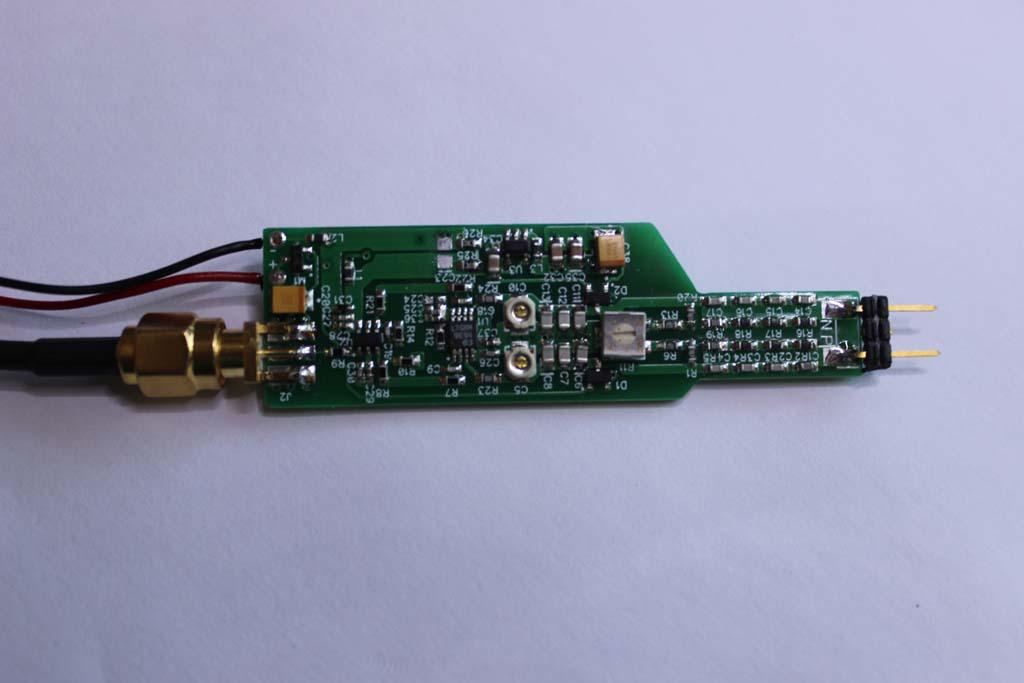 All SMD of course. here are the files for the project including the BOM. 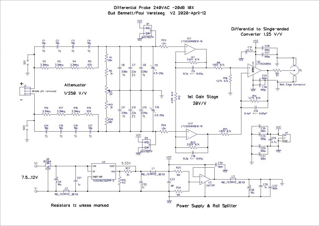 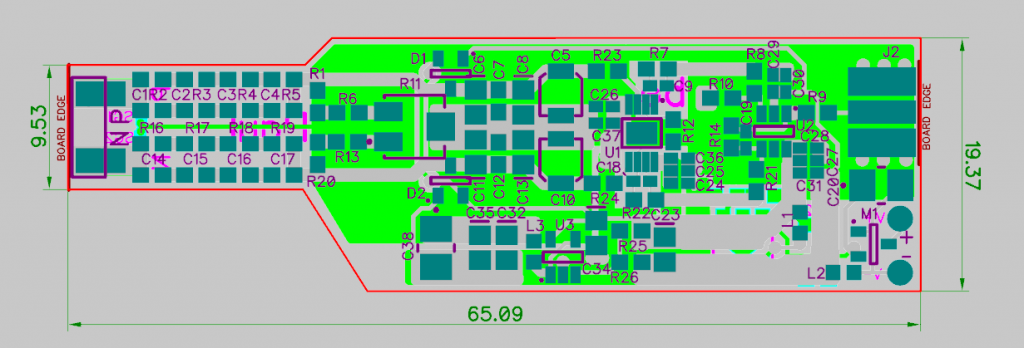 Edited 2021-05-21 08:50 by poida wronger than a phone book full of wrong phone numbers |
||||
| gaspo Regular Member Joined: 25/06/2018 Location: AustraliaPosts: 67 |
|
||||
| phil99 Guru Joined: 11/02/2018 Location: AustraliaPosts: 3317 |
It doesn't but that is not always necessary. As long as the two attenuator divider chains have an adequate voltage rating, as this does, it should be safe. Provided the attenuator end is enclosed in plastic to avoid accidental contact I would use one. |
||||
| gaspo Regular Member Joined: 25/06/2018 Location: AustraliaPosts: 67 |
I've finally built the two probes shown in the previous post, and they appear to be working. However, I'm a bit confused about their measuring capabilities. According to the specifications: - Common Mode Range > ±340V (240VAC produces a sine wave with a peak-peak value of 679V). - Differential Voltage Range > ±25V for 240VAC common-mode, ±25V for 0V common-mode. I have a question about the "Common Mode Range > ±340V." Although the probe has a 1/250 attenuation for working with mains, the signal between the inputs should still be within ±25V; otherwise, it may get clipped. My main question is how and where to connect the probe inputs to achieve a 240VAC common-mode and then measure it accurately. Additionally, I wonder if I still need to use a voltage divider in front of the probe to ensure the signal remains within the ±25V range. 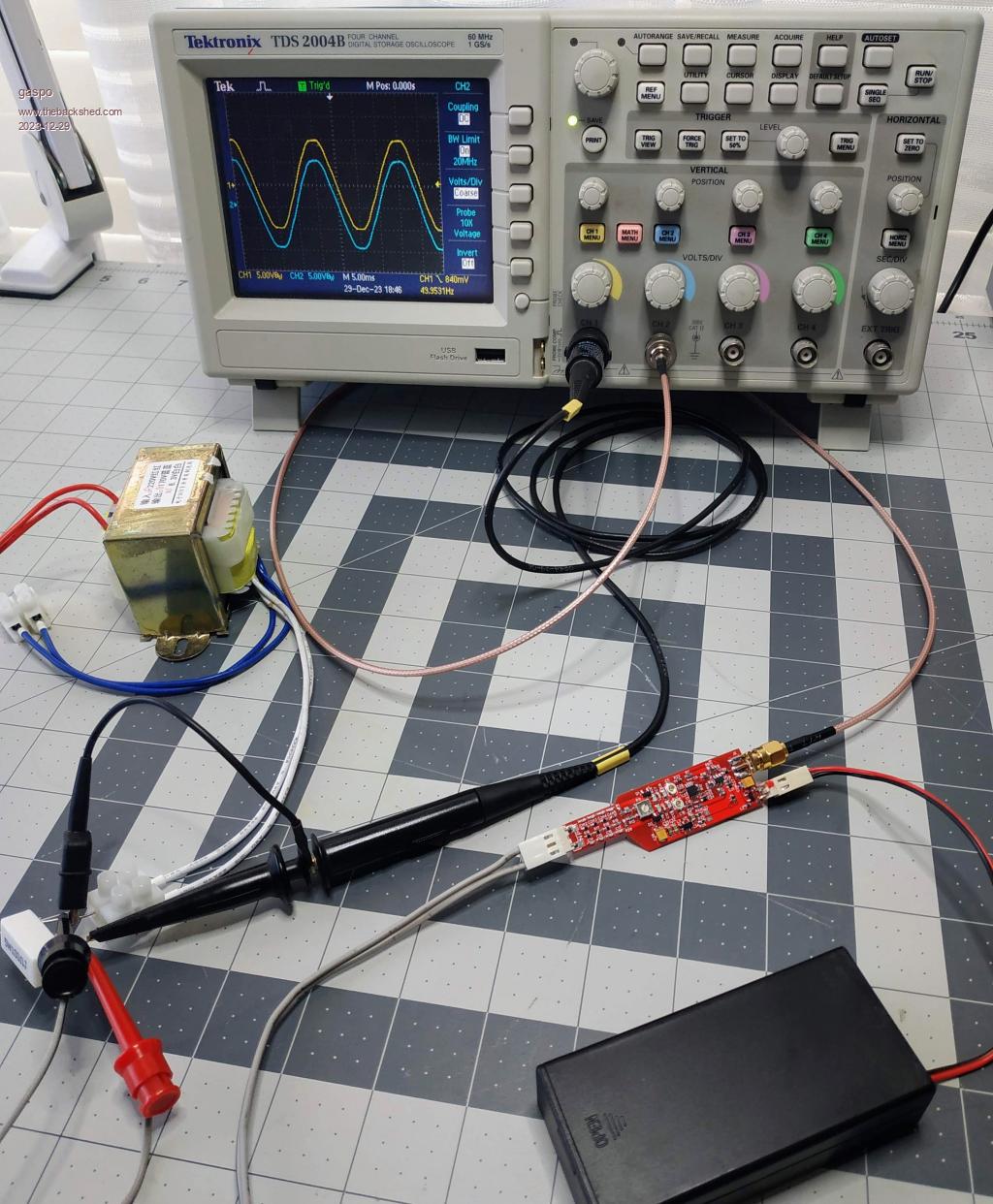 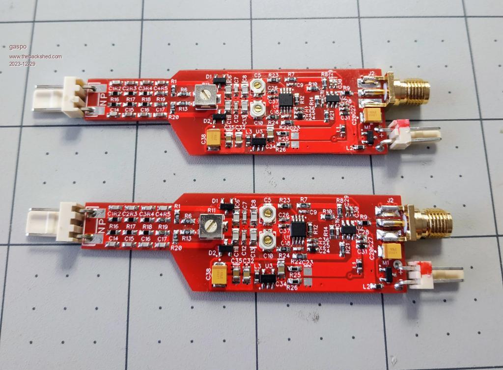 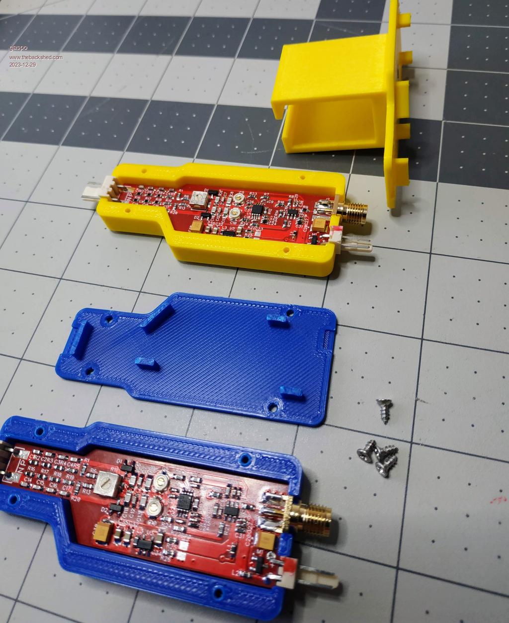 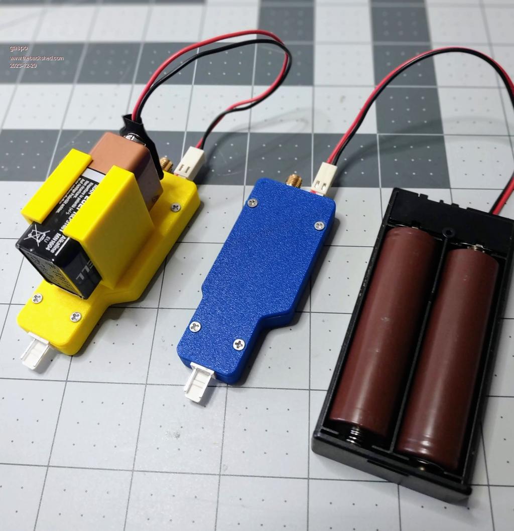 |
||||
| phil99 Guru Joined: 11/02/2018 Location: AustraliaPosts: 3317 |
That is my understanding of how it works. To check connect the inputs to a 30V transformer, if it clips you have the answer. If it does clip in the above test a 10:1 attenuator will be needed to measure a differential of 240V. 1M ohm across the probe tips with 4.5M from each tip to the 240V. For a 50Hz fundamental that may be enough but to accurately read harmonics and spikes small adjustable compensation capacitors will be needed across the 4.5M resistors. Use a square wave to adjust them to remove any rounding or peaking of the edges. Edit Or use a standard probe on the output of a 24V transformer. 20VA or larger for best accuracy. Waveform distortion can become significant under 5VA, though a resistor in series with the primary reduces it at the expense of phase accuracy. Edited 2023-12-30 06:51 by phil99 |
||||
| gaspo Regular Member Joined: 25/06/2018 Location: AustraliaPosts: 67 |
Yes, it does clip the signal when the measured Vpp > 50V. If I still need to use the external attenuator what is then purpose of probe's built-in 250:1 attenuator. Is there a special way of connecting the probe or setting up the circuit in "Common Mode" to be able measure up to ±340V peak? |
||||
| phil99 Guru Joined: 11/02/2018 Location: AustraliaPosts: 3317 |
Without it the op-amps would have 340V on the pins. They don't like that. The probe allows you to measure small differences in voltage on a live circuit. Eg. Many domestic pump controllers use 5V and 24VDC supplies derived from 240V via a series capacitor and bridge rectifier. The DC "ground" is live so this probe would be ideal there. If the voltage difference between your mains neutral and earth is small you could use a regular probe with the earth clip removed. The scope ground will be via its mains earth. Not perfect but often good enough. |
||||
| gaspo Regular Member Joined: 25/06/2018 Location: AustraliaPosts: 67 |
Thanks Phil, I'll use the voltage divider you suggested. |
||||
| phil99 Guru Joined: 11/02/2018 Location: AustraliaPosts: 3317 |
I forgot to say 1he 1M is the total resistance across the probe tips. The probe's attenuator looks to be about 20M so the added resistor will be about 1.05M Edit A simpler option may be to add a 8.8k resistor across the op-amp end of the existing attenuator, multiplying it by ten. Top of R1 to bottom of R20. Put a switch in series with it for two ranges. Edited 2023-12-30 13:46 by phil99 |
||||
| gaspo Regular Member Joined: 25/06/2018 Location: AustraliaPosts: 67 |
That is a good idea; it can be integrated into the enclosure. Just need to apply some 5-minute epoxy to keep the switch in place and prevent it from leaning on the tiny SMD resistors. I used 2K on one end and 6K8 on the other. 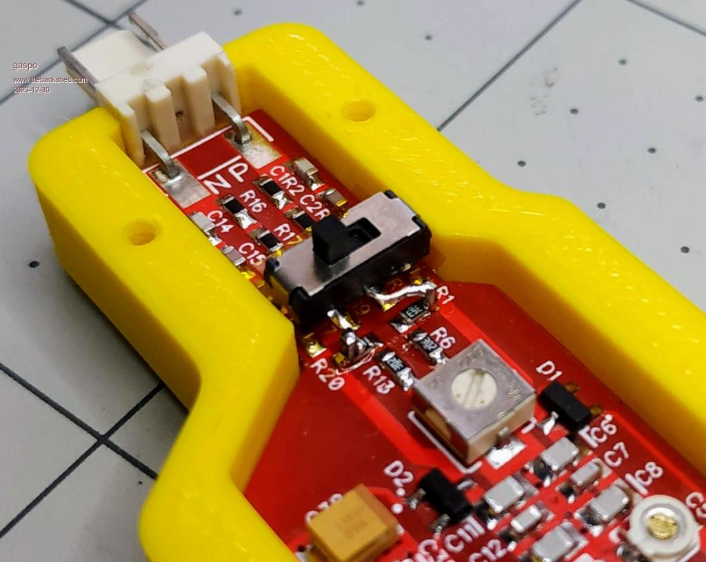 |
||||
| phil99 Guru Joined: 11/02/2018 Location: AustraliaPosts: 3317 |
Looks very neat. I hope you checked the accuracy before gluing it, in case the resistor value needs tweaking to allow for tolerances. If it is already stuck measure any error to calculate a correction factor to apply to readings. |
||||
| gaspo Regular Member Joined: 25/06/2018 Location: AustraliaPosts: 67 |
I'll glue just the switch and leave resistors accessible for adjustment if needed. With the current value of 8.8K the scope measures about 1% more than what the DMM is showing (187Vrms vs 185) |
||||
| Page 1 of 2 |
|||||
| The Back Shed's forum code is written, and hosted, in Australia. | © JAQ Software 2026 |
