
|
|
Forum Index : Electronics : Rafael Inverter project (Poida Powerboard + Picoverter)
| Page 1 of 3 |
|||||
| Author | Message | ||||
| flyingfishfinger Senior Member Joined: 12/09/2020 Location: United StatesPosts: 120 |
Hi there- For the sake of everyone (and my own) sanity, I'll gather everything here instead of asking a bunch of questions in different threads. Firstly please bear with me, I'm new at this (high power electronics) but otherwise come equipped with solid EE skills as my profession(PCB design as well) and have access to a decent lab at work. It's geared towards nano & microamps, but the usual test equipment exists. So, I'd like to construct a 3-5kW inverter to output 120V (I'm in the US) from 24V lead-acid batteries for our off-grid spot. It looks like Peter's new Picoverter and Powerboard will do the job for a fully DIY build. To start off, some dumb questions (or confirmation thereof): General required parts: - Powerboard - Picoverter (+ Nano) - Transformer (DIY toroid) - 2x chokes - (Heat sink) Have I missed anything in the above list as far as major components go? This is what I've taken from reading various threads. Regarding power: What's a reasonable upper limit I can expect to get out of this design? Regarding the transformer: We don't have many (any?) dead inverters / Aerosharps over here to harvest parts from, what kind of core do I need to be looking for? What is used for the chokes? Regarding capacitors: If not new, these can be harvested from ATX power supplies? Regarding PCBs: I use JLCPCB regularly, sourcing boards and parts isn't an issue. I'd like this to be a more DIY, less off-the-shelf project (money isn't necessarily an issue, but we're not out here very often and spending less is better, if that will influence the design in any significant way) Thanks for the guidance I've received so far, I look forward to building this thing! Cheers, Rafael EDIT: Later, I'd also like to build Peter's MPPT but let's keep that separate for now. Edited 2021-05-18 13:00 by flyingfishfinger |
||||
| poida Guru Joined: 02/02/2017 Location: AustraliaPosts: 1480 |
I think I would first look at the loads you expect to have to support. I can only speak from my experience so my house uses about 200 - 500 W for most of the time. There are short peaks of 1,500W when a fridge decides to start up due to their thermostats. Recently, last 6 months, I have added the dishwasher to the circuit and this draws 2.5kW for 3 periods of 6-8 minutes each. Last Saturday is typical. The Red line is inverter DC input power. The light Blue line is battery voltage. Upper Grey line is constant voltage charge target. Black line is fan command, non-zero means it is running. 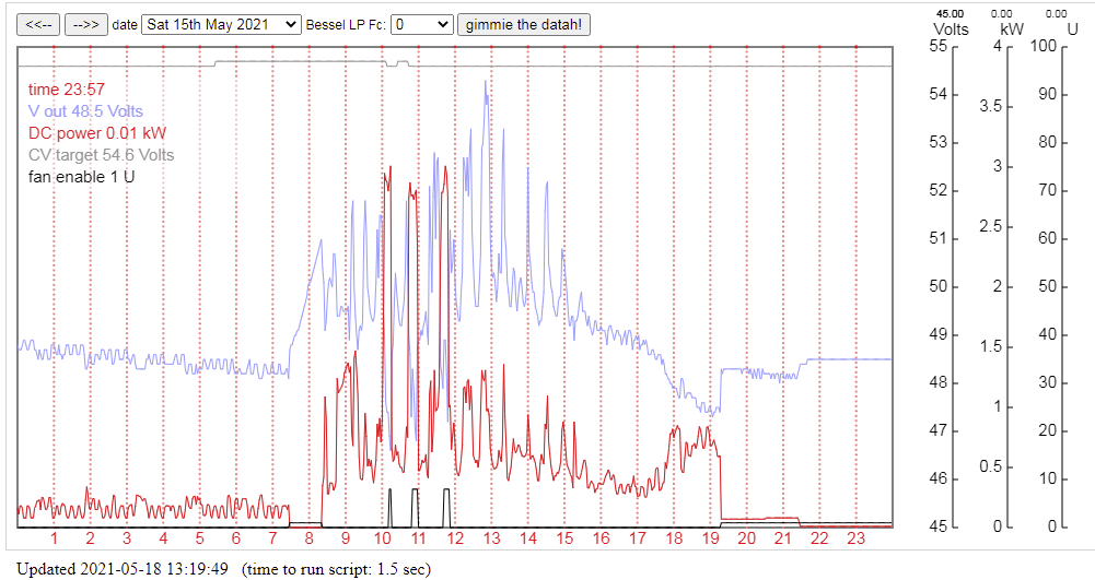 So from the above it would be sensible to make an inverter that is running at it's most efficient when producing about 500W. It spends so little time at the high levels I can afford to have it at a lower efficiency during those peaks. My estimation of efficiency is something like 93% at 500W and maybe 91% at 2.5kW (there are times when the inverter power is zero. This is when the battery voltage drops to below low voltage cut-off and so the inverter is switched off) So, what is your load profile? All day at 3kW? All day at 500W with short peaks of 3 and 5kW? All day at 150W, just a fridge and some lighting, then you cook at night using electricity. 1 hr at 4kW... The home inverter is a 4 x 4 HY4008 power board and in testing I have shown these are capable of well over 10kW peak power. The limiting factor will be heat removal. I chose not to make my own toroid transformer. I use a stock standard 3kW 220V/250V toroid from an Aerosharp. I then wind my own primary over the top of the two existing windings. This forces me to use smaller copper area than I would like. But I can live with the drawbacks of extra heat and a little less efficiency. So my toroid gets hot with 2.5kW and after 5 minutes, the fan is commanded to run. On occasions, maybe when the pool pump is running (1.5kW) and then we run the dishwasher, both fans run - one for the heatsink and one for the toroid. In the above day's graph, the heatsink only peaked at 32 degC and the toroid winding peaked at 49 degC. The nanoverter will also shutdown the inverter due to over temperature conditions so it's quite safe and can look after itself. So look at the load profile first. That might then suggest battery size. Then have a look at your usual day's energy usage, in kW.hr This will also inform the battery size choice. And then you will have enough data to choose the inverter power. wronger than a phone book full of wrong phone numbers |
||||
| poida Guru Joined: 02/02/2017 Location: AustraliaPosts: 1480 |
chokes: I use large Ferrite E-cores, these in particular and I make my own gap of about 1mm. With two of these, and about 6 turns, I get 47uH approx. or about 95uH when in series. I have tested these to show that they do not saturate badly even at about 90 Amps. This is good for my 3kW @ 48V DC inverter. The chokes get warm too so place them where they can get good air flow. There are other ways to go about this. Digikey also have these cores Maybe you can salvage likely cores from somewhere. What is important in my view is the choke retains most of the inductance at high frequencies - of the order of 200kHz - AND this while carrying large DC current. Since the choke's job is to absorb the high frequency power of the PWM square wave and re-release this as smoothed current, the high frequency performance of it seems to me to be self evident. Many of us here have made a choke tester. This is highly recommended. (as an aside, the mppt project of mine has a very welcome other use, that is, it's an excellent choke tester in it's own right) RenewableMark made his chokes from two laminated iron cores. I hope others here will comment further on this. wronger than a phone book full of wrong phone numbers |
||||
| Warpspeed Guru Joined: 09/08/2007 Location: AustraliaPosts: 4406 |
Peter has summed it all up pretty well. For a typical domestic type application, the average power will be quite low, perhaps a few hundred watts. But there will be some massive peaks as inrush current surges as things start up such as the motors in refrigerators, washing machines, and air conditioners. Perhaps even some really nasty loads like microwave ovens and welders. So you need the peak surge capacity, or basically enough mosfet current handling to sustain the peak loads. Heatsinks and transformers take time to heat up, and need to be sized only for constant steady state loads. If you are running off a battery at night, zero load inverter idling power starts to become a very significant factor. The most expensive part of your off grid system will be the battery, and inverter current at very low loads becomes a major part of the battery load at night when not much is running. An inverter with very high idling power will consume many extra night time amp hours, and that will require a larger battery costing BIG DOLLARS. The main factor in establishing very low inverter idling power is the design of the toroidal transformer. Do it yourself home brew winding is where there are some very significant gains in transformer efficiency possible. Winding a toroid is a pain in the bum, but it will get you something you cannot buy off the shelf, and You will save a lot of battery amp hours at night with a much more efficient home wound transformer. Edited 2021-05-18 16:46 by Warpspeed Cheers, �Tony. |
||||
| wiseguy Guru Joined: 21/06/2018 Location: AustraliaPosts: 1297 |
Agree Tony, also trying to incorporate the small but very efficient 2mA to 2mA output voltage sense transformers into the design should remove a few more watts of idle power depending on what iron cored monstrosity it is replacing. At 230VAC in they are typically using just ~ 250mW. I have almost finished a 3 stage modular approach for 3, 6 or 9kW continuous using cheap 1oz 100 x 100 Power FET boards with 4 FETs (half bridge) and choke summed outputs. Bridging 2 sets of Power Boards & chokes doubles the instantaneous capability for just a handful of dollars. - I agree, you dont need the continuous rated large toroid for infrequent large loads. If at first you dont succeed, I suggest you avoid sky diving.... Cheers Mike |
||||
Haxby Guru Joined: 07/07/2008 Location: AustraliaPosts: 426 |
Some appliances are still 230v in the US so maybe a split phase transformer could be used? That's just a 230v transformer with a centre tap. No extra work and no extra costs or materials really. Rafael, out of interest for the Aussies on this forum, can you tell us what appliances are available to you in 230v? Do your microwave ovens typically run on 110 or 230? Can you buy either easily at the shop? What about dish washers, toasters and washing machines? Can you get them in both voltages? I'm just curious that's all. Here in AU we have the same plugs all over the house, with each delivering 10A, though they are protected with 16A breakers so they could or would supply 15A pretty much indefinitely if they needed to. How many amps is a typical 110V breaker? Over here, newer appliances such as washing machines and dish washers heat their own water internally, and only have a cold water connection. You can get ones with a hot water intake as well but they are less common. Is that the same your way? Big transformers do come up on US eBay all the time. I actually had one shipped to AU and it was surprisingly cheap freight! Honestly I didn't think it would arrive due to the cheap shipping, but one day, a month later, a very old dirty truck arrived and delivered it. You need to find a big toroid core, or better yet, 2 of them to stack. It will be hit-and-miss as to what you get so maybe just buy a few and take some pictures, post them here, and we can go from there. Good luck! |
||||
| Murphy's friend Guru Joined: 04/10/2019 Location: AustraliaPosts: 678 |
Can you please supply more details (where from, part #?) for these voltage sense transformers. |
||||
| wiseguy Guru Joined: 21/06/2018 Location: AustraliaPosts: 1297 |
The Parts I used are here they are roughly $1 each. Sorry for invading your post a bit further FF. They will need a small bit of circuitry to rectify and amplify (lift) the lowish level to around the 3.5V(?) required by the nano. You could fit this onto a sub board similar to your current setup and still feed the DC back to your nano - Ill contact you with a bit more info about this soon. Edited 2021-05-18 21:54 by wiseguy If at first you dont succeed, I suggest you avoid sky diving.... Cheers Mike |
||||
| InPhase Senior Member Joined: 15/12/2020 Location: United StatesPosts: 178 |
In the US, clothes dryers, ovens, cook tops, and large air conditioning equipment use 240. Microwaves and washing machines are 120 volts. Larger industrial models can be found for 240 volts, but any domestic appliance below 3000 watts or so will be 120. Also, in the case of clothes dryers and ovens/stoves, BOTH voltages are used. A typical dryer needs 120 volts for the controls and motor, but 240 volts for the heating elements. |
||||
| flyingfishfinger Senior Member Joined: 12/09/2020 Location: United StatesPosts: 120 |
InPhase pretty much said it. In my apartment, the induction stove, oven & kitchen sink garbage disposal (very American thing) run on 240V, but the washer and dryer downstairs use 120V. However, my brother brought me an electric kettle from the UK (240V 3000W) that boils water like magic compared to US kettles. I wired a European outlet into the stove junction box. Well, we haven't built up the site yet. It will be a small place, so I anticipate a fridge, lights, maybe a stove so the below might be accurate. I'd love to have the abovementioned kettle (3kW for a minute or two). However, I DO know that we will occasionally be using power tools, especially early on, when we are building the site up. Those will usually connect to a standard 120V outlet, which are 15A circuits in a regular household. Definitely no welder, but MAYBE a compressor sometime? Nail guns like compressed air. Heating the place will be via a wood stove, it doesn't get that cold here (never freezes) so that's not a concern in the long run. I expect to have a few hundred watts available 24/7 from the F&P micro hydro generator, so this part may or may not be too much of an issue. R Edited 2021-05-19 02:22 by flyingfishfinger |
||||
| flyingfishfinger Senior Member Joined: 12/09/2020 Location: United StatesPosts: 120 |
Oh, found something interesting: 5KVA transformer. It's local enough that I could make the drive to pick it up, so it really only would cost $60. If we look at the last two pictures, they are of a beefy toroid. Could this work? The ratings on the non-toroidal one are much better, though. I can't quite tell if I would get the toroid or the "square" one, but I have inquired... R Edited 2021-05-19 02:47 by flyingfishfinger |
||||
| Haxby Guru Joined: 07/07/2008 Location: AustraliaPosts: 426 |
The toroidal in your link looks like a good start. It's all about the core dimensions and material quality. You won't really know what you have till you take it home and do some tests. If I was you, I'd buy 2 of the toroidals, take them home and run some tests. Unwind/rewind if necessary. Warpspeed is our resident transformer expert and may have more to add. |
||||
| flyingfishfinger Senior Member Joined: 12/09/2020 Location: United StatesPosts: 120 |
It almost seems like I could use the first one as-is, but I'm probably missing something relevant. EDIT: Here's another, , 4.5 inch diameter, 2.5" tall. Too small? R Edited 2021-05-19 06:15 by flyingfishfinger |
||||
| Haxby Guru Joined: 07/07/2008 Location: AustraliaPosts: 426 |
Since you are starting from scratch, I'd strongly suggest choosing the highest voltage batteries you would be comfortable working with. This is usually 48v. |
||||
| flyingfishfinger Senior Member Joined: 12/09/2020 Location: United StatesPosts: 120 |
I'm not QUITE starting from scratch. My little PV system out there runs on a Victron BlueSolar MPPT, which can only charge 12 or 24V batteries and I'd like to keep that. I currently have 2 x 10⁵Ah 12V marine deep cycle batteries in parallel which will be enough for the time being, but I can wire them either way. R Edited 2021-05-19 07:32 by flyingfishfinger |
||||
| Warpspeed Guru Joined: 09/08/2007 Location: AustraliaPosts: 4406 |
Phil is quite right about using a higher voltage battery, or at least giving yourself the future option. What I suggest you do, is wind your toroid with TWO primary windings, and run them in parallel for now for 24 volts dc. Later on that gives you the option of connecting the two primary windings in series for a 48v battery. The rest of the inverter should be perfectly happy to run at either voltage, its only really the transformer that really determines the dc operating voltage. Cheers, �Tony. |
||||
| flyingfishfinger Senior Member Joined: 12/09/2020 Location: United StatesPosts: 120 |
Fair enough! What do you think of the one in the 2nd link I provided above with dimensions? R |
||||
| wiseguy Guru Joined: 21/06/2018 Location: AustraliaPosts: 1297 |
I think the second one is too small for your needs (my guess is only 300 - 400VA). For the price the 5kVA unit is a real bargain, despite the fact you need at least 28VDC to get your 120V AC rated output. Working backwards from a 24V supply you can only generate ~ 17VAC so at full power you will only have ~ 102VAC. But at times when fully charged you will have ~ 27.5V that will transform to ~ 117V AC. I assume most power tools would still work fine with 100VAC and the kettle aint going to boil real quick either. But the rating is for 5KVA, so running at say 1-3 KVA losses will be minimal (certainly less than at 5KVA) and you might get an extra few volts out you weren't expecting. I reckon set the output volts to say 105 and be prepared for it to droop a couple more volts as the batteries draw down. Its worth the $60 from a learning/fun perspective and if you go to pick it up you can have a closer look at all those toroids he has lying around whilst your there, maybe you will strike gold ! If at first you dont succeed, I suggest you avoid sky diving.... Cheers Mike |
||||
| wiseguy Guru Joined: 21/06/2018 Location: AustraliaPosts: 1297 |
Just had another thought maybe you can wire the secondary in series with the driven primary and get back another ~ 17VAC added to the output. Its unconventional but I reckon it would work fine. The output voltage is then not isolated from the batteries any more so safety & attention to accidental grounding etc must all be considered. This is not intended as a long term solution just as a means to an end to get going out in the back blocks. Now you can have at least 115/117VAC and know it will be that for 90+% of the time. I should also add and clarify that our inverters have mostly (all?) used toroids. In that respect you will be a bit of a pioneer. The toroidals are a bit more efficient perhaps Tony could indicate what comparative losses you could expect, I reckon he has more hands on experience than I do in this area. Edited 2021-05-19 13:42 by wiseguy If at first you dont succeed, I suggest you avoid sky diving.... Cheers Mike |
||||
| flyingfishfinger Senior Member Joined: 12/09/2020 Location: United StatesPosts: 120 |
Apparently they're all the same. Too bad, would have been nice to be a "pioneer" :) I think you mistook the first set of pictures. He's out of "rectangular" transformers, only has toroids left: 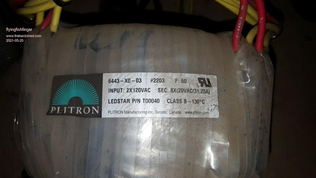 I was able to find a datasheet to go with it as well, attached. How much of this could I use as-is? 644303-1_toroid.pdf R Edited 2021-05-20 03:26 by flyingfishfinger |
||||
| Page 1 of 3 |
|||||
| The Back Shed's forum code is written, and hosted, in Australia. | © JAQ Software 2026 |
