
|
|
Forum Index : Electronics : Reverse engineering the aerosharp igbt driver board
| Author | Message | ||||
Haxby Guru Joined: 07/07/2008 Location: AustraliaPosts: 426 |
After amassing 10 aerosharp inverters over the last year, and playing with warpverter designs, I was thinking it would be fun to re-use the IGBT modules found in these units. The Mitsubishi IGBT modules have a board bolted on top with optocouplers. There are 6 optos for each of the 6 built in IGBTs. There are 2 high side and 4 low side IGBTs per module, so a single H bridge could be made per module. I was thinking of tracing out the pinout of the 2 IDC connectors and designing a board that drives 4 of these modules for a warpverter style inverter. I started tracing the IDC pinout but wonder if anyone can make sense of the circuit that drives each optocoupler: Each one has the below circuit. I don't see what the parallel diode and capacitor do. Any ideas? 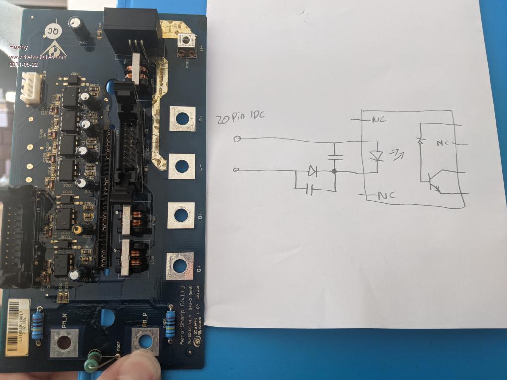 |
||||
| Murphy's friend Guru Joined: 04/10/2019 Location: AustraliaPosts: 678 |
I wish you luck with that project. Some time ago, looking at my pile of Aerosharp IGBT modules, I got their specs from the net and tried to make them work individually (without the PCB) but no luck. There seems to be some protective circuitry in there that must be set just right for the IGBT to turn on. |
||||
| Haxby Guru Joined: 07/07/2008 Location: AustraliaPosts: 426 |
The data sheet looks straightforward. There is no protective circuitry. Just an error out per igbt (but no enable pins or anything). I'm considering just shorting out the SMD diode and cap unless anyone sees any reason to keep it? |
||||
| Murphy's friend Guru Joined: 04/10/2019 Location: AustraliaPosts: 678 |
Thanks, perhaps the module was faulty (a good reason why that aerosharp was junked  ). ). |
||||
| rogerdw Guru Joined: 22/10/2019 Location: AustraliaPosts: 955 |
Haha, funny about that. I went through the same thought process. I'm not that clever ... but I may be able to point you to what they were thinking in relation to the opto coupler drive ... see image below. It points out you need to consult the application note of the optocoupler for detailed instruction of the circuit around the optocoupler. Maybe it will help ... in it's best Japanese English ... Otherwise send me your email address and I'll forward you a copy of the document I pinched that image from. Or is there any way I can post it here in the forum ... it's 1.8Mb 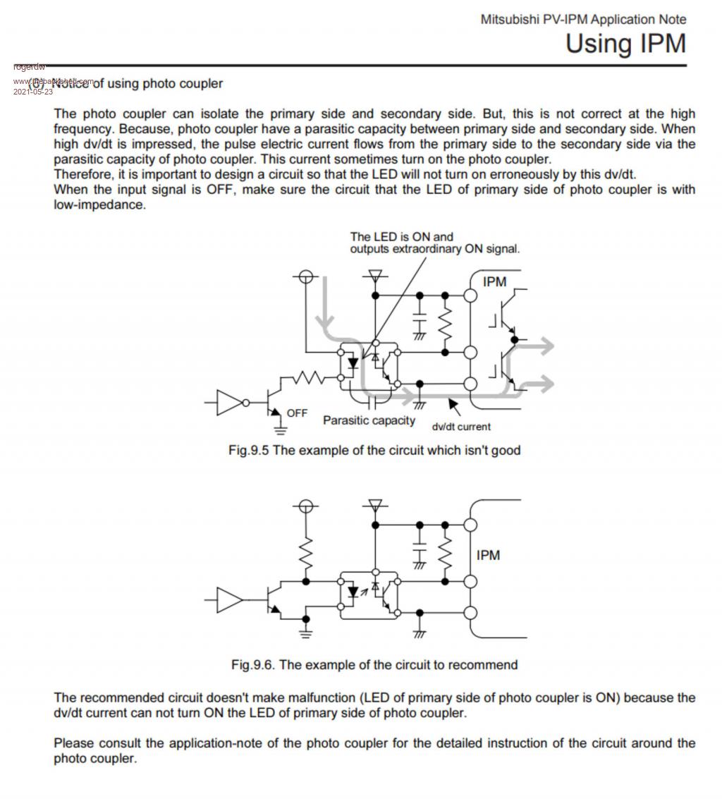 I also spent time trying to understand the overall concept and created a few diagrams ... 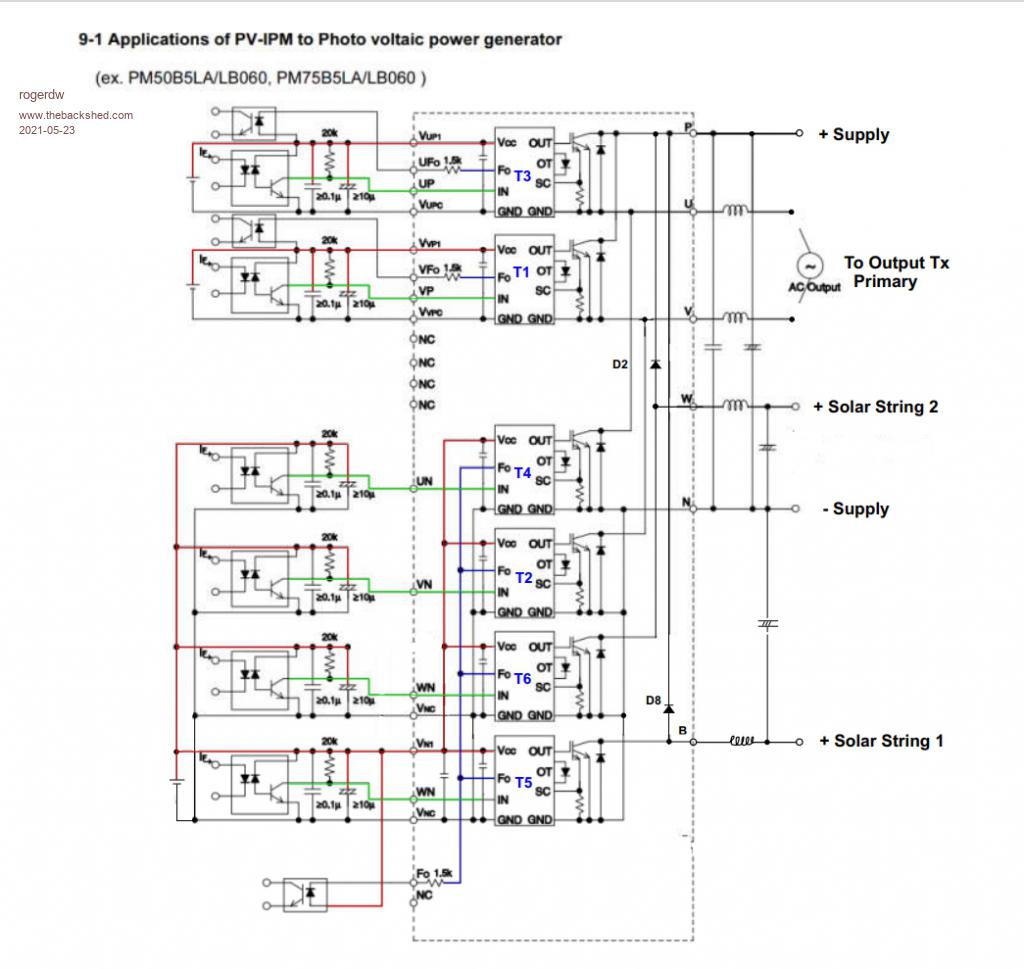 Cheers, Roger |
||||
| Haxby Guru Joined: 07/07/2008 Location: AustraliaPosts: 426 |
Roger you can upload a file with the icon next to the upload picture icon. Would be good to have it here for reference in future. Hmm I never thought of parasitic capacitance through an optocoupler. Very interesting. |
||||
| Haxby Guru Joined: 07/07/2008 Location: AustraliaPosts: 426 |
Roger I sent you a PM with my email if you can't upload here. |
||||
| tinyt Guru Joined: 12/11/2017 Location: United StatesPosts: 561 |
I think this is the link to the appnote. Oops not the exact same appnote, maybe a different document revision. Edited 2021-05-23 09:13 by tinyt |
||||
| rogerdw Guru Joined: 22/10/2019 Location: AustraliaPosts: 955 |
Thanks Phil, I didn't realise we can upload files here. And yes, when I read it I wondered just how many issues people have had over the years might have been attributed to that. I have emailed a few files directly to you, though I'll also add them here if it works, in case there's any discussion. Thanks Tiny, that does look like the same 39 page document .. at least to my bleary eyes atm.  The second image was one I doctored with colour to aid in my understanding of the device and its drive. PV-IPM Application Notes.pdf My Notes on AeroSharp IGBT Module.pdf HCPL-3120 Opto.pdf Cheers, Roger |
||||
| Haxby Guru Joined: 07/07/2008 Location: AustraliaPosts: 426 |
Here is the pinout of the board that sits on the PM50B6LA060 IGBT power module in the Aero-sharp inverters. I had no surprises while tracing the pins. All 6 opto diodes don't share any common tracks. All fault outputs of the module are paralleled after going through separate optos. The pos HV sense and neg HV sense are through onboard resistor dividers. I'll be drawing up a PCB that will use 4 of these power modules for a quick and easy high voltage warpverter style inverter. It will be nice to have current monitoring and fault output indication for every inverter stage. 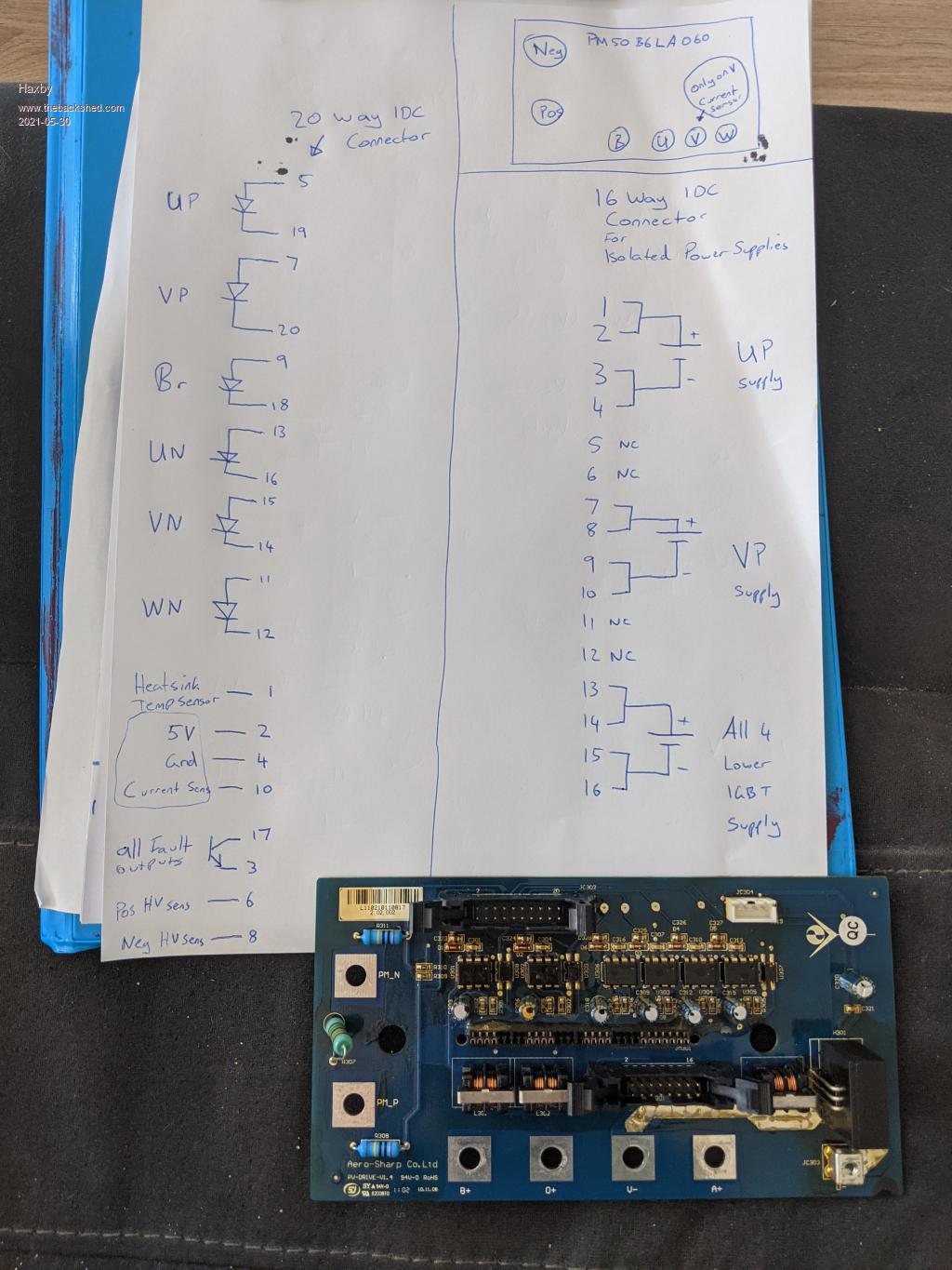 I still haven't worked out why there is a REVERSE diode in SERIES with each opto LED. Maybe it's a zener? I haven't tested it. If it causes trouble, I'll short each one out with a blob of solder. |
||||
| The Back Shed's forum code is written, and hosted, in Australia. | © JAQ Software 2026 |
