
|
|
Forum Index : Electronics : H-Bridge Controller Using Raspberry Pi Pico
| Author | Message | ||||
| Solar Mike Guru Joined: 08/02/2015 Location: New ZealandPosts: 1228 |
Having a go at designing the CPU controller for the modular H-Bridge using the recently released Raspberry Pi Pico. I picked up 5 of these from a NZ wholesaler for $30 odd, seem extremely great value for building any simple control system. Decided to use micro python rather than go down the Picomite route; have never programmed python before, but I have a book that I have never read, been sitting on the shelf for the past 10 years or so. After doing some reading, python is a great fully object orientated language, so after a slow start with the different syntax that I'm normally used to, have managed to get the Pico to output some pretty good SPWM sine waves by making use of the tiny PIO state machines that sit along side the dual cpu's. Using 2 IO pins, each alternately outputting a 180 degree SPWM wave form to suit my power half bridge boards. Here are some images taken from the scope that show the 2 1/2 sine wave forms after passing via a simple RC filter, the other shows the gap between the outputs where they cross over (65 uSec), the SPWM carrier is 23.8 Khz; pretty easy to make it go up to 100 Khz; Pico is running at standard clock frequency. 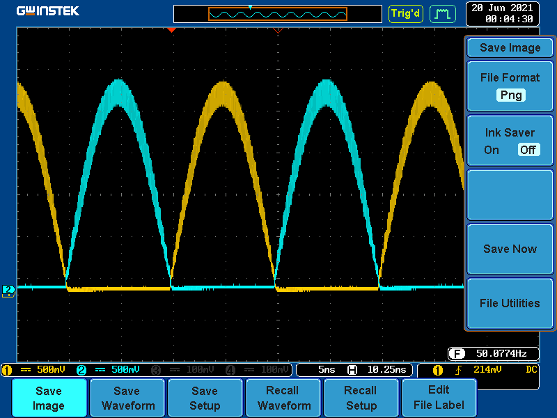 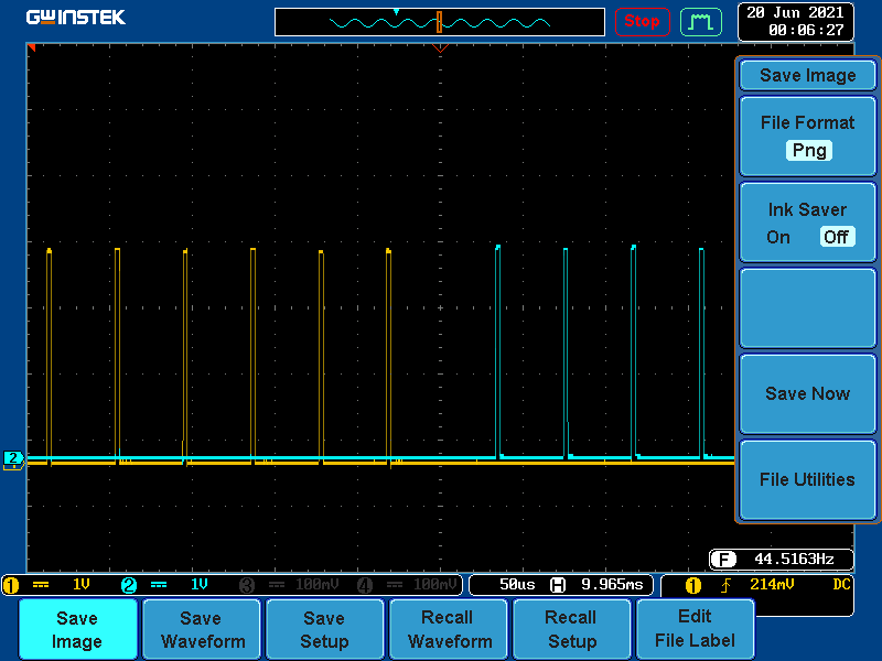 The software creates a table of hundreds of rows of sine 1/2 wave values, each of a differing modulation depth; my intention is to measure the incoming battery voltage and at every 360 degree cycle and select either a higher or lower table row as feedback to counter differing voltages (fast loop). Above that is a slower loop that measures the output AC. Early stages yet, but looks very promising... Cheers Mike Edited 2021-06-19 21:31 by Solar Mike |
||||
| Warpspeed Guru Joined: 09/08/2007 Location: AustraliaPosts: 4406 |
I have had great success with feedforward correction, and see this as very likely the next big step forward in inverter development. Cheers, �Tony. |
||||
| phil99 Guru Joined: 11/02/2018 Location: AustraliaPosts: 3317 |
Yes, feedforward is an excellent choice. In higher powered systems high gain, fast acting negative feedback is usually needed for accurate output control but risks serious instability with reactive loads. Adding feedforward allows a lower gain slower feedback loop. Power stations have used it for decades, for both alternator and turbine control. |
||||
| Planned Obsolescence Newbie Joined: 23/06/2021 Location: AustraliaPosts: 2 |
Nice work! I've been looking into SPWM for a raspi too, I want to build a variable frequency drive for an induction motor to maximise startup torque and correct the power factor at low rpm in the hope of wringing a bit more efficiency out it. I've seen SPWM done on Arduino many times but when you add variable frequency into the mix the coding becomes a bit more complex than a python solution would be (I imagine anyway) Is your code open source or is it proprietary? |
||||
| Solar Mike Guru Joined: 08/02/2015 Location: New ZealandPosts: 1228 |
Here is a sample of the code that generates a spwm lookup table of sine values; each row is in format of a tuple containing 60 values for 180 degrees of a sine wave at a fixed modulation depth using 10 bit modulation. The rows start at 70% mod depth and end at 100%. The data is passed into 2 of the high speed PIO state machines to output the SPWM on gp pins 0 1nd 1. All this occurs on CPU0. CPU1 is used to update the index into the table running on a separate thread, currently it just loops through the mod depths and outputs a number that causes the sine output loop to switch to a different table index; this would be part of a feedback loop. Note code on CPU1 must not use more memory, ie use globals as there is no proper thread OS to manage things. I hade to make use of the garbage collector to free up memory generating the table data, as the PICO was running out. Variable frequency is easily done by altering the sleep_us(value) in the main sine output loop, the current value of 150 = 50 Hz, lowering it speeds up proportionately. Note: this is my first attempt at writing ANY python code, so it may not be the most efficient way to accomplish things, any python experts out there feel free to let me know how to speed it up. Cheers Mike SPWM_1.zip |
||||
| Planned Obsolescence Newbie Joined: 23/06/2021 Location: AustraliaPosts: 2 |
Excellent! I've only been looking into SPWM on a Pi for a few days and there's not much information applicable to the pi mcu, there's quite a bit of info on Arduino so I kept finding a lot of red herrings until I stumbled across your recent post. I salvaged a 240v squirrel cage motor from a washing machine, it doesn't have a start cap just a dual run cap (one for each speed I assume) so it has negligible startup torque. I hoping I can reduce the slip by managing the start frequency until it gets up to about 75% of its working rpm and make it generate a bit of torque at low rpm without needing a massive inrush of current like a motor with a start cap. Thanks for posting your code Mike. |
||||
| Solar Mike Guru Joined: 08/02/2015 Location: New ZealandPosts: 1228 |
Have spent some more time with the PI Pico to see what it can do as an H-Bridge controller, very impressed, python is a very easy language to program in. The state machines are extremely versatile for controlling high speed IO signals. Using both CPU's seems quite stable after standard precautions are taken for threading. Here is the result of setting up two of the PIO state machines to output a full H-Bridge output of SPWM at 24 Khz rate and 50 Hz sine modulation, with 250 nSec dead-time; so 4 IO pins are used for bridge drive. Four waveforms Yellow = L0, Blue = H0, Purple = L1, Green = H1 After 180 degrees the L0 signal remains high and SPWM applied to the other H1, L1 and vice versa. 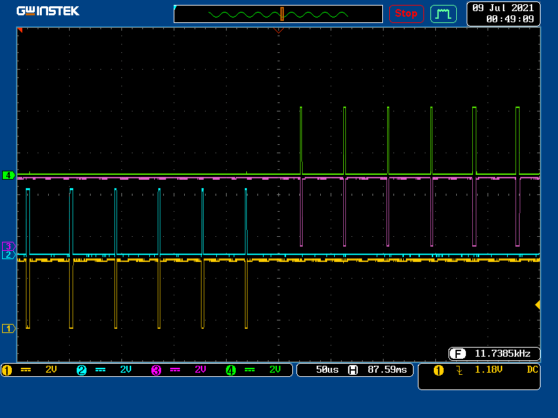 Here is a blowup of last 180 degree pulse showing the 250 nSec approx dead-time 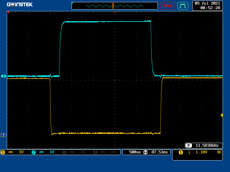 I have synchronized the start of the state machines by setting their control register, so the wave forms are very accurate and easily setup in software; this means I can now dispense with the dead-time inserter module pcb, and buffer the cpu signals directly via 3.3:5v logic gates with a disable input to control the drive to the cross-coupled opto couplers on the power boards. Its looking very good. Cheers Mike |
||||
| Solar Mike Guru Joined: 08/02/2015 Location: New ZealandPosts: 1228 |
Have finally started drawing up the schematic for the Pico controller, I wont go any further using plugin breadboarding as the layout is chaotic at best and worse, awful with high speed logic signals; so will move straight to final pcb. This part of the schema is for the SPWM drive and power supplies, decided to use FAN3229TMX driver buffers for the multiple parallel opto power board modules as they have minimal delay and good matching between devices, these drivers are made for mosfets, but will work well here with a fast logic OR gate that works with 3.3V acting as an AND gate with 0 input logic to give a drive that will prevent any shoot thru should the cpu not play ball with its SPWM + dead-time output. Pico ADC reference is a precision 3.0V reference chip MCP1501 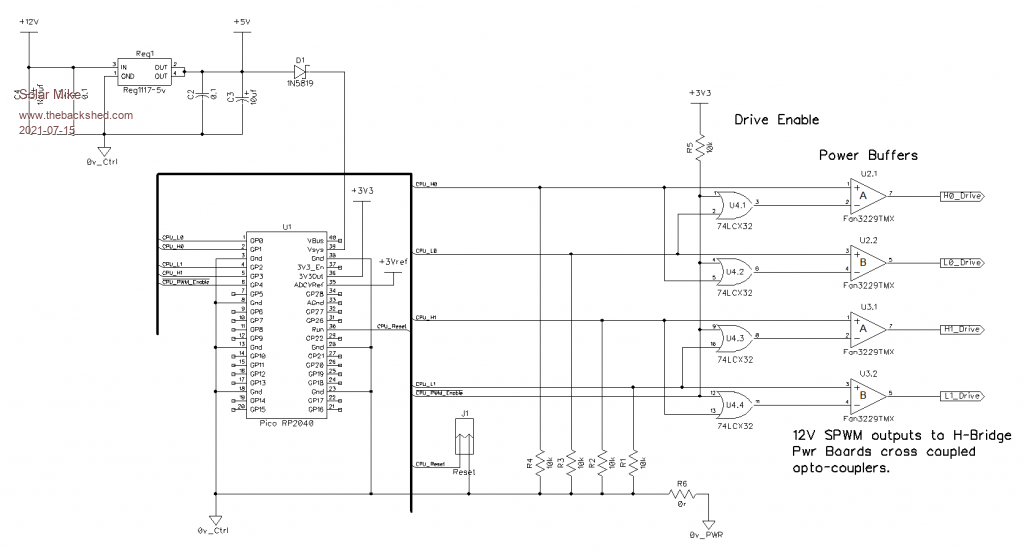 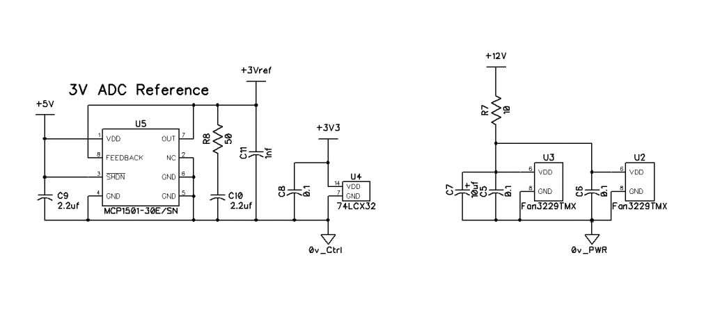 Will look at the voltage and current sensing next. Cheers Mike |
||||
| Solar Mike Guru Joined: 08/02/2015 Location: New ZealandPosts: 1228 |
Have made more progress on this project. For analog measurements the Pico doesn't have enough ADC inputs, so will use an analog multiplexer with a common output noise filter going to a single ADC. Temperature measurements, will use the MCP9701 active linear thermistors, have used these before, they are great. AC voltage measurement, will use a ZMPT100B 2mA voltage sense transformer coupled to an active full wave rectifier\peak detector. DC battery voltage sensing is a simple resistive divider, the DC voltage selects the 50Hz modulation depth of the H-Bridge, feed forward. Current measurement goes to a latching trip circuit, to inform the CPU an overload has occurred, I'm not going to measure it for any display purposes. 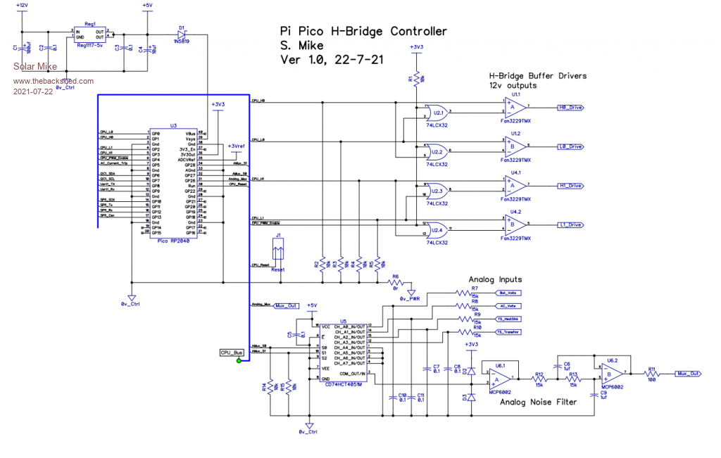 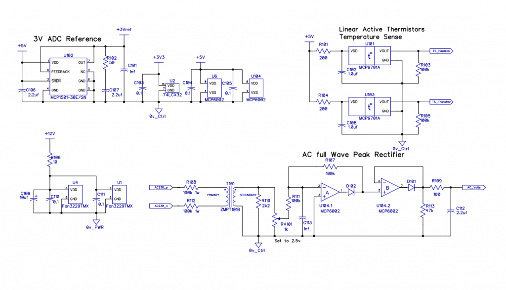 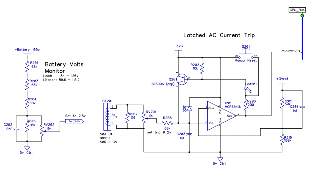 PicoController.pdf To do: Outputs for status running, LED's, LCD display, HBridge modules Main Caps pre-charge, 1-Wire network., external shutdown input. Feel free to comment on the design, no doubt there are better ways to implement some of this. Cheers Mike Edited 2021-07-22 20:23 by Solar Mike |
||||
| wiseguy Guru Joined: 21/06/2018 Location: AustraliaPosts: 1297 |
Is anybody out there........... ? Hi Mike, have been following your posts with interest I like your progress with python. We have very similar VFeedback and IMax circuits independently created. I have been slowly working on my Pico version using the nano. Fyi below 2 sections of circuit which are very similar to yours! Small critique, consider put R110 & Rv101 (upper part)in series so V feedback cant be accidentally set to zero. Obviously values will need re reworking. Voltage Feedback 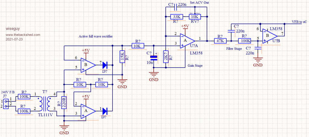 Overcurrent 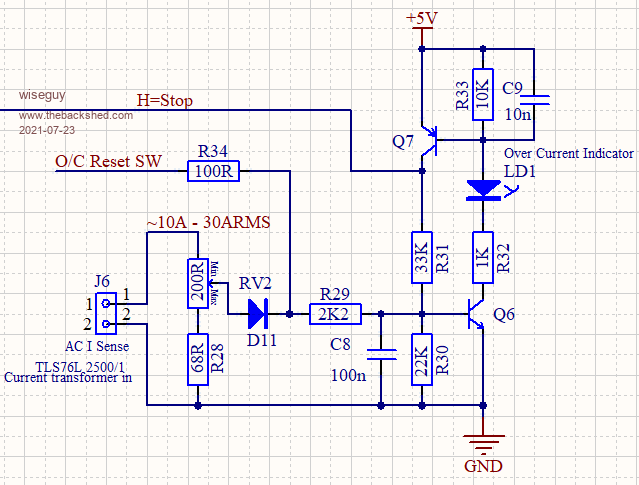 Edited 2021-07-23 19:22 by wiseguy If at first you dont succeed, I suggest you avoid sky diving.... Cheers Mike |
||||
| Solar Mike Guru Joined: 08/02/2015 Location: New ZealandPosts: 1228 |
Hmm very similar in concept, must be on the right path then... Im using Rail\Rail cmos op amps so resistor values are different. Hopefully I can keep using the Pico, it comes with a number of broken features that haven't been fixed to-date by the creators; the dual processor threading has a lot of problems in their software implementation making using the 2nd CPU problematic. The timer interrupts cause issues also, seems interrupts are seriously broken in the Pico. Hoping these will be fixed in a future core software update, they sound a bit like Microsoft. Cheers Mike |
||||
| Solar Mike Guru Joined: 08/02/2015 Location: New ZealandPosts: 1228 |
This is what I'm thinking for outputs. Main Caps Pre-charge: 2 relays, contacts in series for switching battery volts via a 100R 50W resistor. I wanted 2 sets of contacts to give me 100V rating. Main Inverter Contactor: Vacuum 400A 12V relay switched by larger mosfet. Cooling Fan: small mosfet can switch the 12v 600mA fans. Some status and fault leds, small loud pcb piezo alarm, tiny relay for external output that the inverter is on\off line. All the above driven from a 74HC595 serial to parallel shift register running at 3.3v, the mosfets are spec'd for 3.3v drive. 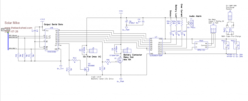 Cheers Mike |
||||
| Solar Mike Guru Joined: 08/02/2015 Location: New ZealandPosts: 1228 |
I think cct is now ready to start a PCB layout, I have used up all the Pico's pins, mainly so I can experiment with the Pico for other projects. Any errors will get picked up in pcb design layout. Most of the additions are to the outputs, I have used a couple of Bi-directional 3.3-5v converters so I can use 5v logic I2C, serial devices. 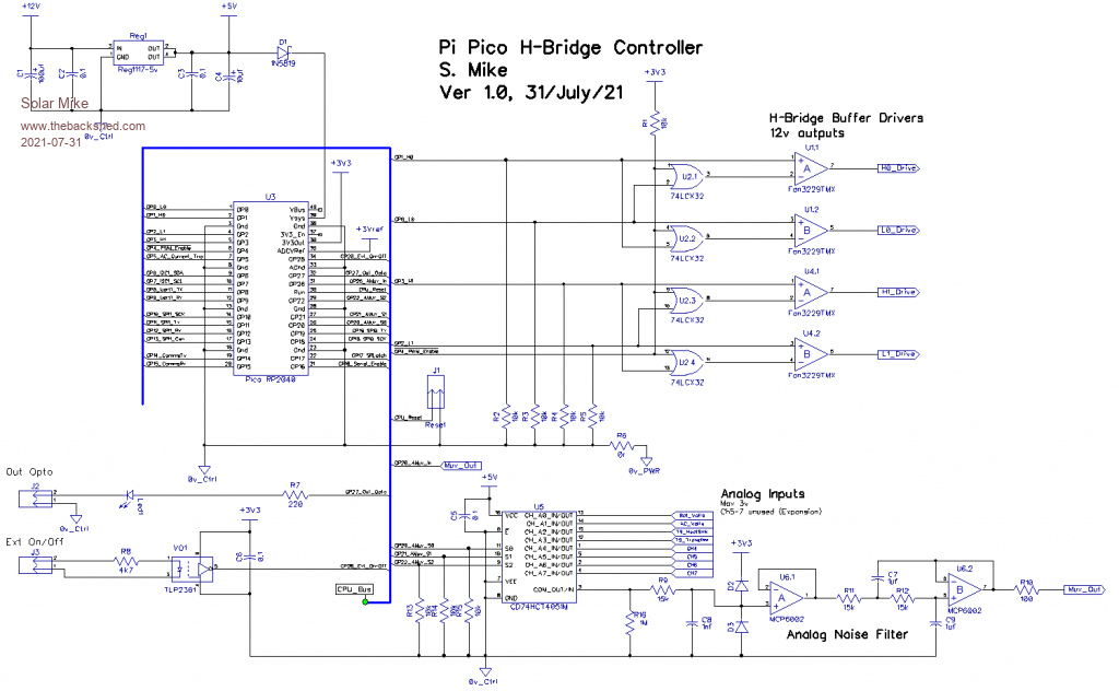 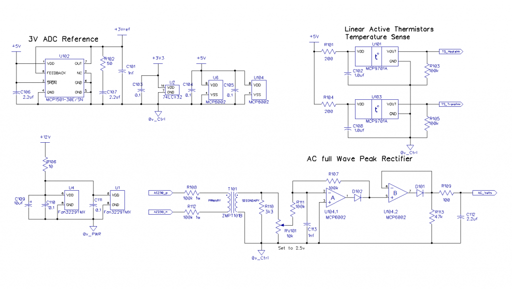 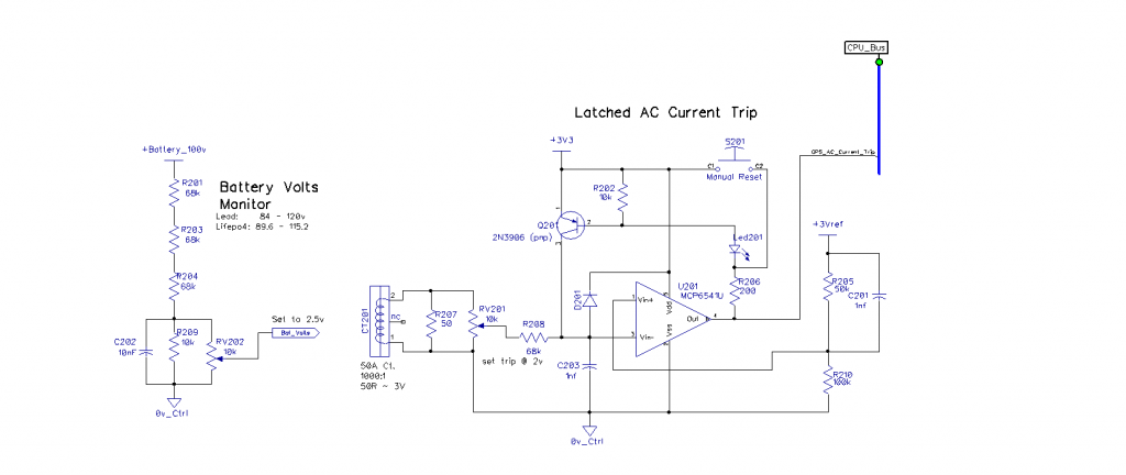 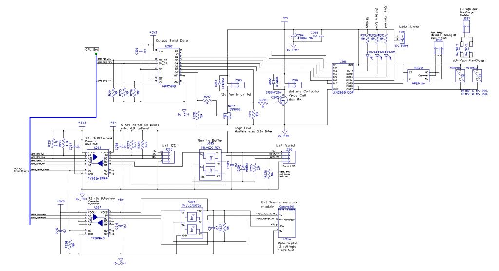 PDFsam_merge.pdf Mike |
||||
| Solar Mike Guru Joined: 08/02/2015 Location: New ZealandPosts: 1228 |
Haven't started on the PCB for this project, so taken the opportunity to re-visit the schematic; made some alterations to simplify a few things. New schematic below: 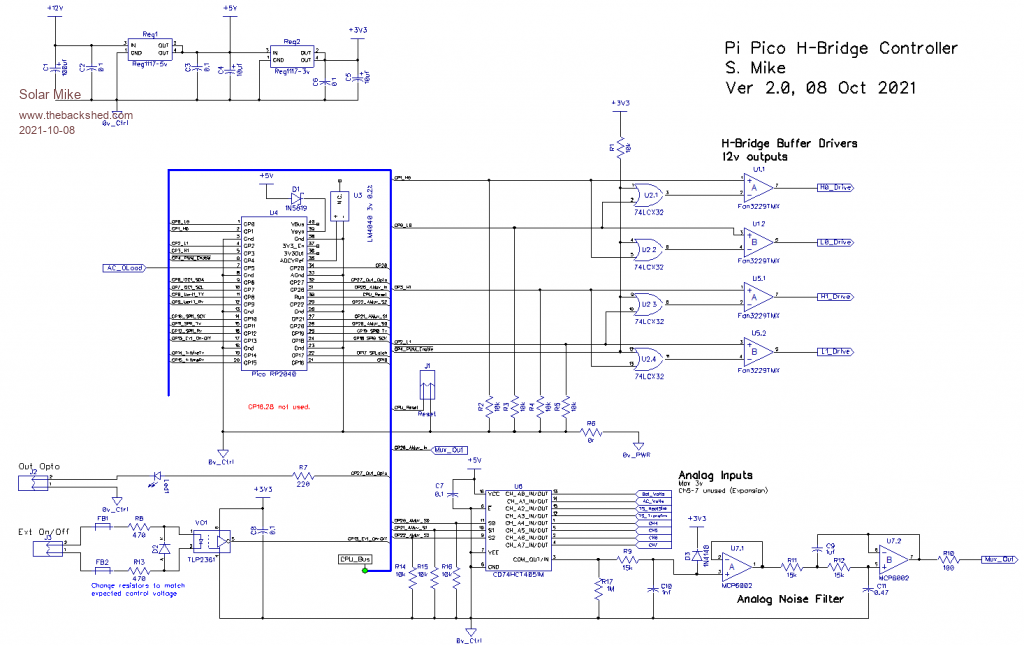 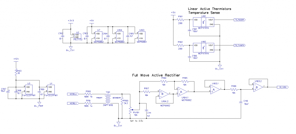 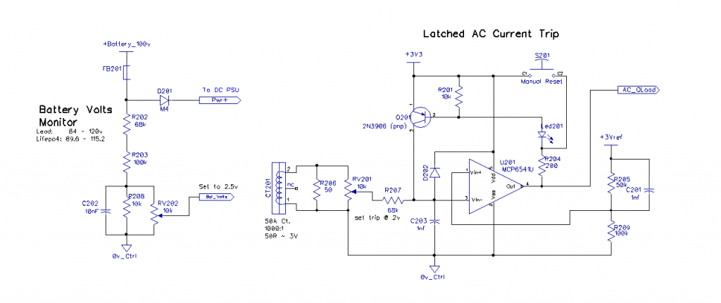 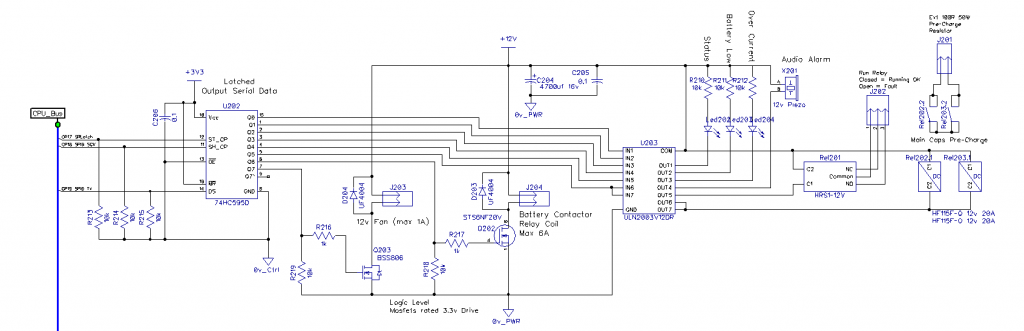 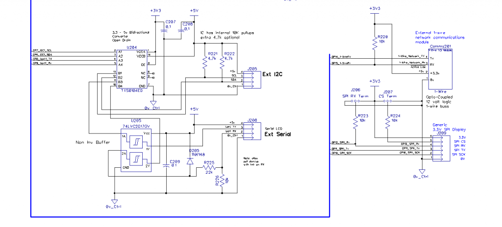 Cheers Mike |
||||
| scruss Senior Member Joined: 20/09/2021 Location: CanadaPosts: 102 |
In addition, the ADC isn't as clever as they hoped it would be. There are workarounds in later bootroms (and I hope/assume in the SDK). More details: ADC ENOB (large PDF link, sorry) |
||||
| Solar Mike Guru Joined: 08/02/2015 Location: New ZealandPosts: 1228 |
Interesting they publish specs using an external low noise voltage reference, BUT the board as sold doesn't have this, it uses the noisy switch mode 3.3V supply rail. No wonder the module is so cheap. First thing I did was fit the LM4040 3V reference IC for the ADC reference, will see how that goes. Cheers Mike |
||||
| Solar Mike Guru Joined: 08/02/2015 Location: New ZealandPosts: 1228 |
Finally have gotten around to designing a PCB for the controller, in the process have made numerous small changes to the schematic, happy with the pcb as is, could be improved a bit, but with 30 hours effort to date it will do for testing. Top 150 x 160mm: 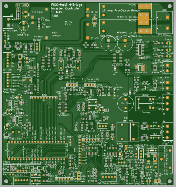 Bottom: 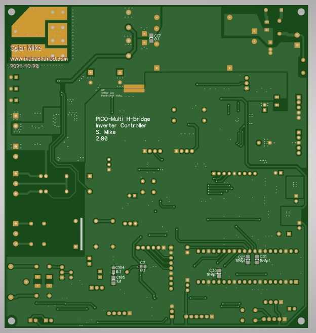 Will post new schematic next. Cheers Mike |
||||
| The Back Shed's forum code is written, and hosted, in Australia. | © JAQ Software 2026 |
