Notice. New forum software under development. It's going to miss a few functions and look a bit ugly for a while, but I'm working on it full time now as the old forum was too unstable. Couple days, all good. If you notice any issues, please contact me.
Revlac Guru Joined: 31/12/2016 Location: AustraliaPosts: 961
Posted: 12:03pm 01 Jul 2021
Copy link to clipboard
Print this post
Thanks Pete, That certainly gives me some good direction and very helpful. Number of wires in parallel....after looking at them they are a fine guage for the current rating, so definitely more than one wire, the wires are covered up to the terminal ends, so hard to see until taking it apart.
Anyway will get to this some other day.
Something I think may be of interest...or maybe not. I did see for sale a generator head made up from an old 3 phase squirrel cage motor, now the rotor was the usual 2 or 4 pole slip ring rotor, replacing the original rotor. My Assumption: A small transformer 240/110?(As the exciter) was placed on the output neutral and active, this was used to supply the regulator, control the power to the brushes and rotor. Not sure if that was the full story, I expect it might be a bit difficult to regulate as the power it taken from the same wires that are powering a load, Having said that, I see the exciter winding on one of the small 3phase generators is connected to the three phase winding's, or perhaps that's shorted inside, will find out some other time. Just wonder if that idea would work as a generator of sorts.Cheers Aaron Off The Grid
Davo99 Guru Joined: 03/06/2019 Location: AustraliaPosts: 1577
Posted: 12:49pm 01 Jul 2021
Copy link to clipboard
Print this post
Very interesting! If that worked it might be possible to turn a Single bearing gen head into a twin bearing for belt Drive.
I bet the odds of Finding a motor and a Gen head with matching specs so the clearances and lengths were right right would be like winning lotto.
Are you familiar with Induction motor generators? You simply put capacitors across the legs of a ( prefrably) 3 Phase motor, energise it and drive it over rated speed around 10% and it will generate.
I have built a couple and definitely works however the power regulation is... basically non existent. It's controlled by the engine speed and caps mainly. Works perfectly for a Fixed load where you can tune the caps and or engine speed but no good for loads being turned on and off.
There are controllers that are basically dump loads. They keep the same load on the machine at all times and simply increase or reduce the surplus power as required. They tend to be DIY from what I have seen.
If one had a relatively fixed load maybe like a battery charger that could run full load then switch off maybe just for brining a low pack up to 80% or something would be fine but there is little load variation available. You can crash the generation by overloading it. The voltage will start to fall and then the magnetic field in the motor will just crash. You can also wire them up so you get single phase off a standard 3 wire output.
I want to set one up for back feeding the mains. When over spun a motor works as a generator very well with power connected to them. In that scenario, no caps or anything else needed, Just wire them as Normal. You can even use the electric motor to start the engine then speed the engine up and it will generate.
Godoh Guru Joined: 26/09/2020 Location: AustraliaPosts: 378
Posted: 10:55pm 01 Jul 2021
Copy link to clipboard
Print this post
Hi Aaron, seems that they just took an induction motor and turned it into an alternator. With wound rotors as motors they used to add resistance to the rotor circuit on start up to reduce starting current. Then as the motor came up to speed the resistance was lowered and eventually the slip rings shorted out. It then ran like a squirrel cage motor. Electronic and transformer starters have basically done away with those old soda tank and secondary resistance starters.
For an alternator, power is tapped off the output and fed back into the rotor to regulate the output voltage ( as you surmised). The machine will start generating from residual magnetism and as output voltage builds it then feeds current into the rotor. Some machines had transformers to feed lower voltages into the rotor.Depends on the rotor winding. Older portable generators had slip rings too, some fed DC to the field ( stator) coils and took power off the rotor, Car alternators work opposite, the rotor is DC fed by the regulator and the stator is AC 3 phase that is rectified to charge the battery.
So if the machine has only 2 or 4 salient pole pieces on the stator ( just one piece per coil) then the Stator is DC. If the Stator has multiple slots with many coils then it is AC and the rotor will have just 2 or 4 coils on it, and will be fed DC. Hope this is not too much info Pete
phil99 Guru Joined: 11/02/2018 Location: AustraliaPosts: 1781
Posted: 07:59am 02 Jul 2021
Copy link to clipboard
Print this post
To get stable voltage when using a squirrel cage motor as a generator the traditional method is to run it in parallel with an existing generator or inverter of similar or larger capacity, boosting the total power available. When the engine runs it up to 4% faster than synchronous speed it generates rather than consumes power. Pushing it past 4% may exceed is max. current rating. Synchronous speed being set by the original supply. This was often done during WW2 to augment the power mains.
Davo99 Guru Joined: 03/06/2019 Location: AustraliaPosts: 1577
Posted: 09:13am 02 Jul 2021
Copy link to clipboard
Print this post
I -thought- the asynchronous speed was higher than that. Never really worried, I go by a meter on the output not a tachometer. As a motor is Circa 1500 RPM and an engine is 2200+, easy to speed the engine up till you get the output and go from there.
I have never run one with a Generator or even thought of the idea. At first impression it seems like a good way one could bump up the power from a Genny. I would assume one would have to be careful to make sure there was enough load so the IMAG didn't overpower and try to push back to the genny.... if it would try. More the IMAG supplies the less the genny will have to but if the IMAG was pushing excess voltage, perhaps could be a problem?
Anyone done this or have any thoughts? Would there be any protection that could be put on the genny to stop any problems such if a load suddenly was dumped creating an excess of power in the circuit?
Been looking up IMAGS on YT. Very frustrating. The majority of Vids are " Free energy" Crap click bait that pull an amazing amount of a specific group of people in whom hail the most ridiculous setups and the best thing they have ever seen. Some of these vids get several million hits in a year and many people wanting more info. Pretty sad really.
Very few vids on real, good information on them. Edited 2021-07-02 19:16 by Davo99
Revlac Guru Joined: 31/12/2016 Location: AustraliaPosts: 961
Posted: 09:41am 02 Jul 2021
Copy link to clipboard
Print this post
No problem Pete, not too much info for me, easy to understand, I'm pretty sure I have an Ac generator on the back of an old welder, that has Dc stator poles and AC from the slip rings picked up by the brushes, so an easy reference to look at.
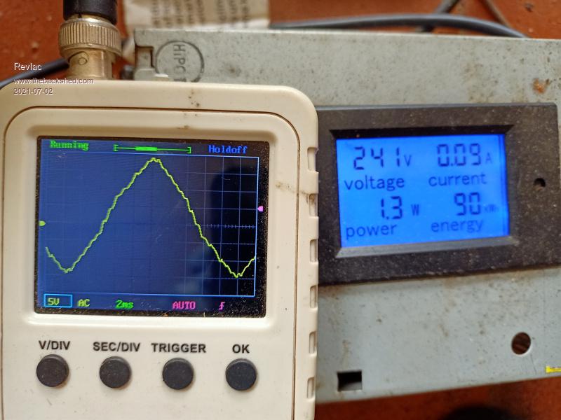
Tried the little Taurus 2200w generator today just out of curiosity, its much like the GMC and others, it has run the house during grid power outage, no grid anymore as the chainsaw went through the powerpole (fastest cut Its ever done) it has been been used to test motors etc and was used a lot doing running power tools drills down the back doing a big fencing job.
First is the the generator unloaded.
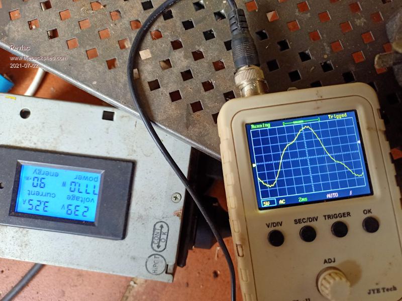
Now a load of 700w, not looking nice.
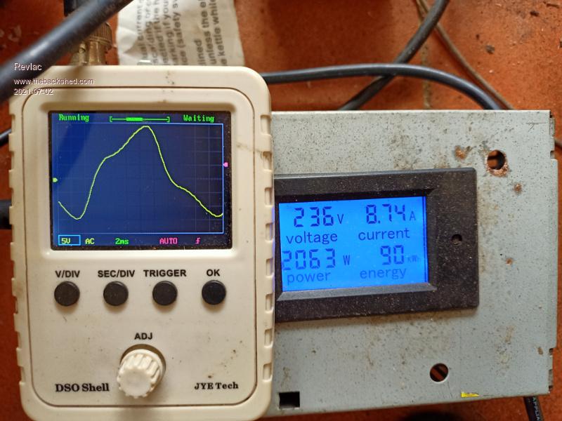
Now tried running the kettle not looking good either, took out the circuit breaker after some time.
The AVR on this unit, I expect its the common half moon shape that can be found for sale anywhere, so many others probably use it as well.
Davo,
I have tried it once but never when any further due to already having a good 3 phase genny, still interesting though.Cheers Aaron Off The Grid
Davo99 Guru Joined: 03/06/2019 Location: AustraliaPosts: 1577
Posted: 12:29pm 02 Jul 2021
Copy link to clipboard
Print this post
Yeah, no point.
For the uneducated ( Me) what are the ramifications of having the less than optimal outputs on a Genny? I know what the waveforms SHOULD look like but what are the problems when they are less than perfect and how much variation matters?
I have had the discussion many times about power and generator outputs and the idea of "Sensitive" electronics. I honestly don't know what they are? Computers, Tv's and a Load of other things these days all run inverters or transformers with very good filtering in the power supplies. I have run computers for hundreds of hours off crappy inverters and generators as well as other things and never had a problem. Resistance loads don't care what you throw at them so I wonder what is actually " Sensitive" these days in a household use?
Are the drawbacks of poor wave forms in lesser efficiency or your clock won't keep good time ( if it's old enough) or??
Revlac Guru Joined: 31/12/2016 Location: AustraliaPosts: 961
Posted: 01:24pm 02 Jul 2021
Copy link to clipboard
Print this post
Yeah, most things will run fine with a bit off wave, also the filters will take care of some noise and odd stuff with other appliances switching.
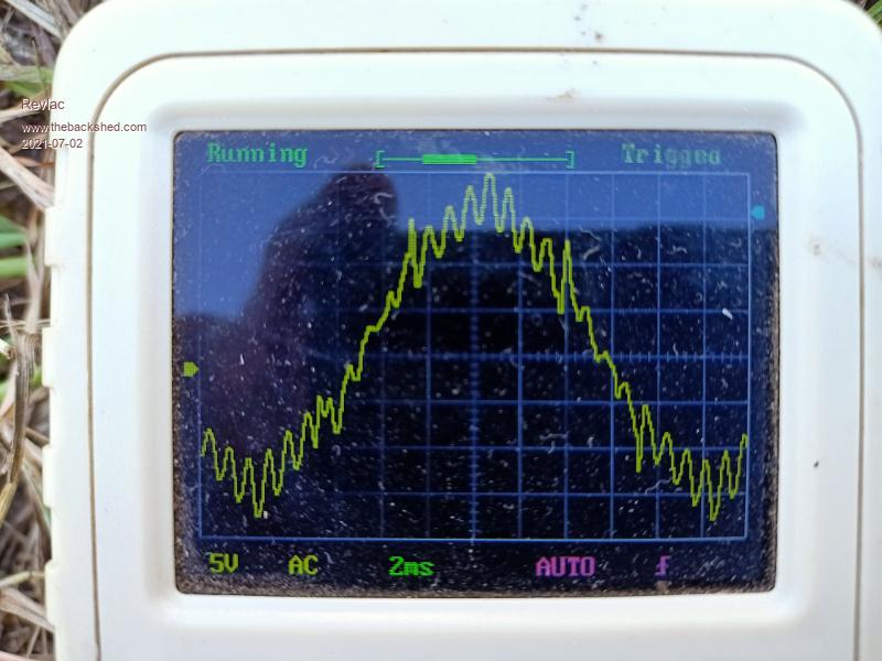
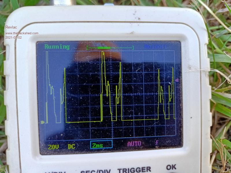
Other situations such as the following. This is the wave off a little Markon generator that is having problems...Several problems, You can see its quite rough, and this in a short time started to burn the capacitor filter in the power meter that was connected, once the filter is burnt out....
Others here might have some explanation's on other effects or it might not be a problem many things.
And here is the voltage at the brushes on the slip ring, AVR is having a fit.
I will fix this one day but don't have time at the moment.Cheers Aaron Off The Grid
Godoh Guru Joined: 26/09/2020 Location: AustraliaPosts: 378
Posted: 11:04pm 02 Jul 2021
Copy link to clipboard
Print this post
Thanks for the scope pictures Aaron. It seems that Poida's generator is pretty good compared to those cheap Markon ones. I know the regulators that you talk about, they are pretty cheap, I guess that with the price comes pretty crappy waveforms too. Seems that there are plenty of spikes in the waveform. Most universal motor type powertools won't mind, except their speed controllers may object. Cheers Pete
phil99 Guru Joined: 11/02/2018 Location: AustraliaPosts: 1781
Posted: 12:19am 03 Jul 2021
Copy link to clipboard
Print this post
To Davo re induction generator.
The problem of excess power when there is a sudden decrease in load solves it's self when in parallel with another generator. Any back-feed from the induction generator to the synchronous generator causes it to speed up, decreasing the speed difference between the two thus reducing the induction generator's output. The induction generator's output only has a small effect on the main generator's voltage. When in parallel with an inverter there needs to be load sharing feedback control of the throttle to ensure no power flows back to the inverter.