
|
|
Forum Index : Electronics : Simple current limit indicator circuit
| Author | Message | ||||
| astroboy Newbie Joined: 28/12/2014 Location: AustraliaPosts: 38 |
Hi Would it be likely that the circuit below would work for limiting current and indicating when the set limit is reached? If so, your explanation about how this circuit works would help me to understand it. Thanks John 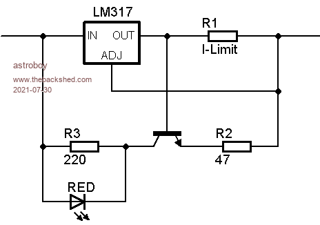 |
||||
| Warpspeed Guru Joined: 09/08/2007 Location: AustraliaPosts: 4406 |
The voltage across R1 will increase proportionally with current, up to 1.25v where the LM317 will prevent any further current increase beyond that. That part will work fine. The transistor will begin to conduct whenever the base emitter voltage exceeds about 600mV, or roughly about half the full load current. In other words the current through R3 will then gradually increase, and the voltage across the LED will also gradually increase with load current. At some point (?) the LED may begin to light up, or it may not, depending on a whole lot of component tolerances, especially the operating voltage of the LED. Big voltage difference between different sizes of LED, as well as the manufacturer and batch. So its a pretty hairy circuit that might work or might not. If you build ten of them, expect different results from unit to unit. Edited 2021-07-30 15:38 by Warpspeed Cheers, �Tony. |
||||
| phil99 Guru Joined: 11/02/2018 Location: AustraliaPosts: 1773 |
Agree "Big voltage difference between different sizes of LED, as well as the manufacturer and batch. So its a pretty hairy circuit that might work or might not." I think the purpose of R3 is to set the point at which the led glows. Replacing it with a 1k trim pot would allow for LED variations. |
||||
| Warpspeed Guru Joined: 09/08/2007 Location: AustraliaPosts: 4406 |
Yup. Cheers, �Tony. |
||||
| bob.steel Senior Member Joined: 27/02/2020 Location: AustraliaPosts: 188 |
How would you make sure it will work? Make R3 adjustable? Edited 2021-08-03 16:32 by bob.steel |
||||
| Warpspeed Guru Joined: 09/08/2007 Location: AustraliaPosts: 4406 |
Well you could try that Bob. But the LED will still start getting brighter and brighter long before it hits current limit, then stops getting any brighter once at current limit. If you want something where the LED stays completely off, and then switches to full brightness right at current limit, this circuit will never be able to do that. Cheers, �Tony. |
||||
| Solar Mike Guru Joined: 08/02/2015 Location: New ZealandPosts: 1122 |
Perhaps by adding an additional diode D3, so Q2 wont start getting turned on until approx 1.2v; then add a constant current source to run the indicator led, will do the trick. An idea off the top of my head, untested of course. 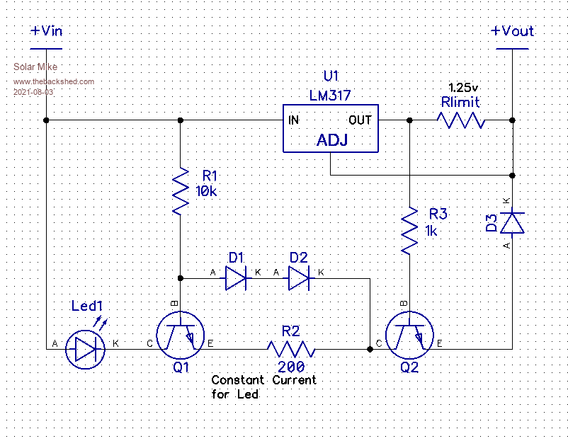 Cheers Mike |
||||
| BriggTrim Newbie Joined: 13/08/2021 Location: United KingdomPosts: 1 |
HI.. Add a Resistor in corresponding with the LED to diminish it's affectability. You would have to tentatively decide its worth yet it ought to be in the neighborhood a few hundred ohms or thereabouts. https://www.7pcb.com/ Edited 2021-10-15 02:10 by BriggTrim |
||||
