Notice. New forum software under development. It's going to miss a few functions and look a bit ugly for a while, but I'm working on it full time now as the old forum was too unstable. Couple days, all good. If you notice any issues, please contact me.
poida Guru Joined: 02/02/2017 Location: AustraliaPosts: 1480
Posted: 07:45am 16 Aug 2021
Copy link to clipboard
Print this post
I was chatting with Wiseguy a while back when discussing a DC load for a KW sized Lithium battery at 3.7V (250 Amps) when I wondered about linear mode MOSFETs.
I made a nice little DC load using the NEC K3304, 2 FETs driven in parallel. It has proven to be a ripper unit, so useful with playing with dc-dc converters, testing various situations etc. The NEC K3304 were not chosen by any selection process. I had 3 of them from ripping an old plasma TV to bits. Since I had them, I used them in the DC load. I did not have even one clue about safe operating areas and thermal run-away at that time. It has been bullet-proof. Talk about beginner's luck.
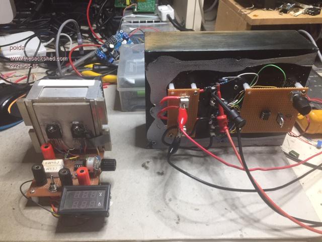
here it is on the left. The new one is on the right.
The little load can take about 30V at 6 Amps forever, no problems. This is 120 Watts
The new one uses some modern Ixys L2 linear MOSFETS. In particular, the IXTK200N10L2 which are 100V 200 Amp devices meant for linear applications. They cost $50 each. I must have been drunk at the time so I bought 2 of them. Blame it on the home-brew vodka.
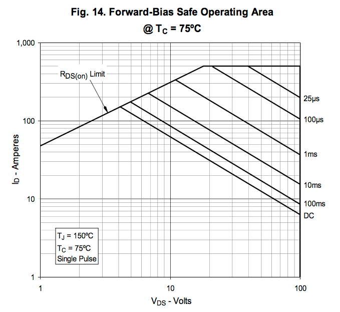
The guaranteed safe operating area is shown in the specs for a CASE temperature of 75 Deg C and that is what I will use as the limit. I can measure case temps with a finger or a temp probe etc.
Below in the IXTK200N10L2 specs we can see the max power is 600W at 75 C. I have two IXTK200N10L2 FETs, driven with individual current sense op-amp outputs so that means up to 1200W if I watch the case temp closely.
20 Amps at 30V, 60 Amps at 10V etc.
I wanted to make a bigger DC load and one that had a much lower resistance. (the little one is 1 Ohm.) The new one is 4 milli-ohms Much better. With 1 Ohm you can only draw 3.7 Amps from a 3.7V Lithium battery. Now it's like 900 Amps not that I want to do that.
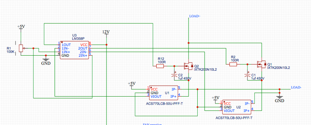
The circuit is so simple
Using a LM358 as a comparitor, take the 0 - 5V signal from a current sensor as -ve input, a 0 - 5V output from a potentiometer as the +ve input and the output goes to the FET Gate, via a 100R resistor and 1uF cap filter (to stop oscillations)
I soldered the current sensor onto the FET source pin. Using 2mm house 240V cable I have a very short and low resistance DC load path.
It works well. Twist the pot and dial up the Amps from 0 to 50 Amps But you need to be mindful of the power. I always have to decide what power at what Amps before the pot twist. Maybe a microcontroller could help here.
Anyway, it was a fun Monday to build this. I can now heat up the big heatsink quite quickly. This is 1/2 of a 1.5kW Aerosharp HS.
I have always had an interest in heat and heatsinks etc. Like, WTF does thermal resistance mean? Evidently there is a nice analog to Volts Amps and Ohms (V = IR etc) in the thermal world.
Thermal Resistance, Heat flux and temperature
With the next 2 weeks of lockdown I can start to play with this stuff and get my head around heatsinks, thermal resistance etc.
In a previous post I did a bit of this in the development of the mppt project. Using 2 IGBTs I could get from Jaycar, I ran them in parallel producing a known amount of heat and then see how the heat sink temp rises, then falls when the fan is run, etc.
I think it's time to get a bit more serious with heatsinks.
Oh and by the way: What a difference thermal paste makes.
(all this is driven by the need to know how large a heatsink needs to be. It's so easy to "just make it huge". Sometimes there is not the space. So what then?) Edited 2021-08-16 17:46 by poidawronger than a phone book full of wrong phone numbers
Solar Mike Guru Joined: 08/02/2015 Location: New ZealandPosts: 1228
Posted: 10:50am 16 Aug 2021
Copy link to clipboard
Print this post
Very 'cool' project there Poida.
I have used DIY heat-pipes in the past to remove large amounts of heat energy from a small area to external remote heatsinks; a 1/2" pipe will move 1Kw heat energy to external heatsinks 1M away.
Ones I made were evacuated copper tubes using a sub micron vacuum pump, the vapor transfer medium being plain water.
Cheers Mike
Warpspeed Guru Joined: 09/08/2007 Location: AustraliaPosts: 4406
Posted: 01:26am 17 Aug 2021
Copy link to clipboard
Print this post
Water cooling works pretty well too.Cheers, ĀTony.