
|
|
Forum Index : Electronics : plc as a dump load controller ?
| Author | Message | ||||
niall1 Senior Member Joined: 20/11/2008 Location: IrelandPosts: 331 |
hi all i,ve been experementing with this thing lately and it might make a good dump load controller , i havent been able to blown it up yet which is a good sign 
most automated stuff in factories runs of something similar ..this one runs of a 24v supply ..its pretty obselete now ... its just a section of inputs (24v on\ off switches) on top with outputs (relays) on the bottom..the software (in the background) connects one to the other .theres no actual hard wireing between the two the software lets you do that any way you like , theres all kinds of stuff in there timers, latches ,counters ,resets and no rules as to how you use them .....after your finished you can just download to the plc and its a stand alone unit ....catch is how to turn the inputs into a battery voltage moniter , the little comparator circuit on the right is almost trying to do this but its getting a little hot and bothered and is the best i can come up with (i think the ic in the monitering circuit isnt matched properly to the plc inputs) .......i tried putting a small pnp transistor on each output pin ( the output drops to 0 when the comparator switches over) but the chip is still getting hot after a while ....the plc seems to like a fairly strong clear 24v signal on each inputs so if theres any electronics heads out there with some ideas on this bit of the puzzle ideas would be great... niall |
||||
oztules Guru Joined: 26/07/2007 Location: AustraliaPosts: 1686 |
Try higher value resistors in the pull up circuit. The comparator shorts the pull up resistors to get 0 output. If the resistors supply too much current , then the comparator will heat up trying to short them to ground. I assume they require very little ma to drive the unit's inputs for a high bit.. so maybe 10k pullups will cool the chip back down, without too much degradation with the outputs... is it a lm393? .........oztules edit that should be lm339.... butterfingers Village idiot...or... just another hack out of his depth |
||||
| GWatPE Senior Member Joined: 01/09/2006 Location: AustraliaPosts: 2127 |
Hi niall1, A plc will have probably 1-2A contacts on the relay outputs. You will probably need more current switching than this. I have a NHP-alpha, with 4, 9bit resolution analogue/digital inputs and 4 relay outputs. This unit has all the bells and whistles with programming, including a 4line LCD. As your plc has only digital inputs, and you are supplying a digital signal, then you may as well switch the diversion load directly. You have not mentioned any other logic functions that you may need to interface with it. As oztules has mentioned, if you have an open collector type comparator, high value resistors will be OK. You need to check the input specs to see if series resistors and pullup resistors will be required. Are these inputs OPTO coupled, or bipolar transistor type? Gordon. PS Edit: there are rules to ladder logic. Most programmers do have basic checking of logic. Modern plc's have a real time connected simulator function to test more complicated logic elements and general functioning of the code. You may need to buffer the output of your cct. become more energy aware |
||||
| niall1 Senior Member Joined: 20/11/2008 Location: IrelandPosts: 331 |
hi guys and thanks for relpying ...heres so more info i should have included before this is the comparator circuit 
its running at 24v so i changed the zener to 10v and its shunt to 1k , and added bigger resisters to the leds ( they dont pull much power maybe 20ma in total) at each o\p i added a 500r resistor to drive a small pnp 2n2907 its emitter goes to the 24v the collector to a plc i\p , ...as far as i can tell the plc has photo coupled inputs needing about 5ma , how do i add the pull up resistor ? can i tweak the circuit a bit more ? my theory on how transistors work is ....lets say limited.. when driving the four inputs the chip is using over 100ma which seems a bit high ,but i,ll check the data sheet about this the plan hopefully is to let 6 or more relay,s fire the gates of individual power fets each having their own dump heater element..so the dump load could be ramped up in stages fets and me dont get along very well ,especially in pwm ,this might be a simpler approach the plc maybe could put timers on each relay to smooth out the operation of fets ,maybe even an option to do an emergency shutdown of the mill if the voltage spiked for too long ? ,the shut down option is why i,d really like to get it working "no rules" was a bad description gordon your right ...i can only use the software at its most basic level , i hope to be able to use the minimum of functions to get a program in there , niall |
||||
| oztules Guru Joined: 26/07/2007 Location: AustraliaPosts: 1686 |
Niall, I had a lengthy discussion on using the 339 for this type of application here. here This should answer all your questions. It may be useful to change your circuit to using the non-inverting inputs to get hysteresis like Methanolcat had to. If you still have questions, then ask away, I will see if I can help ..........oztules Village idiot...or... just another hack out of his depth |
||||
| niall1 Senior Member Joined: 20/11/2008 Location: IrelandPosts: 331 |
great link oz ...exactly what i was looking for ,time to get the veroboard out again then niall |
||||
| niall1 Senior Member Joined: 20/11/2008 Location: IrelandPosts: 331 |
heres the new circuit .. pull up.. feedback et all based on the diagram and info in the link ..much better than the old one far more positive trip point ..clear on off much more like a digital signal ..the controller should like this a lot better 

niall |
||||
| oztules Guru Joined: 26/07/2007 Location: AustraliaPosts: 1686 |
Glad to help a fellow chainsaw man. .......oztules Village idiot...or... just another hack out of his depth |
||||
| GWatPE Senior Member Joined: 01/09/2006 Location: AustraliaPosts: 2127 |
Hi niall1, I am about to make a new, dual over voltage controller for my F&P mill. This will only have 2 voltage comparators with a manual override switch. I was to use analogue, but have decided to use a picaxe now. There will be some logic and timing delay functions, and maybe a sticky indicating LED. I will buffer with a logic mosfet to drive the main 200V mosfet that shorts the mill through a separate 3phase bridge above the capacitors. I could have used the alpha plc, but current draw is a little high. Gordon. become more energy aware |
||||
| niall1 Senior Member Joined: 20/11/2008 Location: IrelandPosts: 331 |
hi Gordon reading your new overvoltage project has shown a basic problem i should have seen in what i was aiming for i was thinking of latching on the full dump load to hopefully stall out my machine if it went above a certain voltage ...but the batteries are still in the loop so they,ed just drain into the latched elements , need to rethink this one a bit niall |
||||
| oztules Guru Joined: 26/07/2007 Location: AustraliaPosts: 1686 |
Monitor the batteries with the opamp, but use a separate rectifier for the dump load, that way it does not see the batteries.... problem solved? .......oztules Village idiot...or... just another hack out of his depth |
||||
| niall1 Senior Member Joined: 20/11/2008 Location: IrelandPosts: 331 |
almost finished circuit ...working nice and definately not overheating the chips ...sensing circuit trips roughly beteen 27v to 28.2v spread over six comarators running at about 50ma ..plc 50ma as well ..decoupling caps on its power supply lines seemed to help it,s accuracy although any kind of pwm (old dodgy home built attempt) dump controller on the batteries drives it crazy , (board layout wouldnt be the best) i was thinking about some kind of relay for battery isolation if needed ,an extra rectifier sounds safer ... so if i,m thinking right here the rectifer allows power through to the battery for charging but stops it returning to the windmill line which the dump can be used on  niall |
||||
| niall1 Senior Member Joined: 20/11/2008 Location: IrelandPosts: 331 |
putting the plc dump experiment to bed was held up by one last shot at the pwm controller , being a sucker for punishment i couldnt let it get away with frying all those fets without one more attempt ....so armed with some new fet driver chips and inspiration from the link below this is the new fat free version http://www.fieldlines.com/story/2007/7/14/21428/3703 
the circuit board added on the left uses comparators as a battery voltage monitor and a heatsink temp switch for the fan....so far its behaving ok dumping a nice linear 0 to 25 amps spread at 27v....if anyone could advise on drawbacks , mistakes (or anything else) in the schematic , that,d be great as i,d really like to make it as stable as possible the 2n feedback transistors were tried on a bread board by a kind of ...put it in and feel the tempreture method  ,it takes about an increase of about 1v on the battery to bring the 2n3904 on hard enough to drag the 5v chip reference v down to near zero so ramping up the pwm rate for the fets ,this is pretty quick but suits the sealed batts i use ,it takes about an increase of about 1v on the battery to bring the 2n3904 on hard enough to drag the 5v chip reference v down to near zero so ramping up the pwm rate for the fets ,this is pretty quick but suits the sealed batts i use
in the schematic the frequency tuning of the chip is controlled by a 100k pot ...in this layout the fets like to pulsed at low frequency (almost audable) ...the fets could go from being very happy to really pissed off if the frequency was to high niall |
||||
| GWatPE Senior Member Joined: 01/09/2006 Location: AustraliaPosts: 2127 |
Hi Niall, I am surprised that you need a fan on the mosfets. The 6 mosfets should have only a few watts dissipation each. Most [>95%] of the power should be dissipated in the load resistor. I had a similar single set point control on my battery. I now have a battery maintenance system, that gives Boost, float, absorbtion and equalize programmed voltages and boost and absorbtion times programmed. Batteries will reduce capacity if they are treated badly in the charging area. Gordon. become more energy aware |
||||
| niall1 Senior Member Joined: 20/11/2008 Location: IrelandPosts: 331 |
hi Gordon the fets definately heat up some ,it,d be nice to get a scope put on it to see whats going on the fan is being run slow to get rid of the noise when it cuts in ,but seems to work well with the heatsink...it might be interesting after a while to remove the batts altogether and see if it can used as a stand alone ,kind of variable voltage heating dump for the mill.....the circuit should tolerate set points up to 38v (the mill could go to star) ...........not just yet though ... 
i,ll give it its day in the sun first niall |
||||
| GWatPE Senior Member Joined: 01/09/2006 Location: AustraliaPosts: 2127 |
Hi Niall, I don't drive a mosfet driver this way. The 2k2 pulldown resistor is very slow. The 4420 is a level shifter and works best with a digital 0-5V input level. The output changes to a high when the input transitions through 2-3V and low when input transitions through 3-2V. There is no point in using 12V input logic levels to the 4420. The heating in the mosfets is caused by the slowly changing input to the mosfet driver during the turn OFF phase. A mosfet works best with fast on/fast off switching of course. You would be better to use 5V for the open collector on the 494 and reverse the logic. The irf640 is a fairly old device and will perform better at 0-15V gate voltages. The 4420 is good for this. The only redeeming point of slowly switching a mosfet is a reduction of RFI, at the expense of switching component, heating. In this case you are just heating a wire, so no big deal to heat the heatsink as well. You will only see the switching waveform with a CRO, or DSO, or similar instrument. Gordon. become more energy aware |
||||
| niall1 Senior Member Joined: 20/11/2008 Location: IrelandPosts: 331 |
hi Gordan thanks for the explaination ! for me the data sheets often have too much info on how these things work i,ve made the following changes 5v on the 494 collector.............. pull down resistor on the ic input is now 470R hope this is right march latest circuit 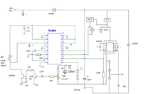
edit april (irc and buildyourownturbine mods) 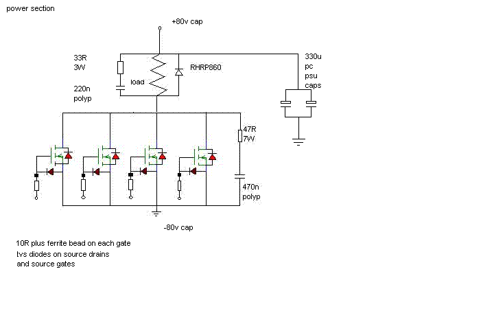

replaced battery with 80v 10,000uf cap ...the 47R resistor was added after the 470n cap started to swell 
..this seems to help the new cap stay cool while the resistor heats up ..i seen similar things on scraped power supply fets ...have no idea how it works also the freewheel diode on the load gets hot when the controllers dumping large currents or a steady mid range ,i think theres either voltage spikes being created by my type of load  (now fully covered with stainless wire) (now fully covered with stainless wire)
or the poly cap across it is affecting the diode ... niall |
||||
| GWatPE Senior Member Joined: 01/09/2006 Location: AustraliaPosts: 2127 |
Hi Niall, You seem to have shares in the 3terminal regulator market. There is a 5V reference supply built into the 494, and the 4420 only needs a bypassed zener supply. You don't need to operate over a wide voltage range, and you only need low currents, so a resistor/zener reg is fine for the 4420. In this appliucation, reversed logic may be compromised by the dead timing of the chip. The success will be determined by reduced power dissipated in the mosfets. I only use heatsinks as a last resort in my designs. SMD components are difficult to heatsink as well. Gordon. become more energy aware |
||||
| niall1 Senior Member Joined: 20/11/2008 Location: IrelandPosts: 331 |
hi Gordan i even have some of the high hv tl783 ones  ... ...
the 494,s were all from dumped pc stuff though 
the temp sensor circuit for the heatsink has a led indicator which will be usefull for seeing how the fets are behaving temp wise after the changes (still on the old trip point).....its ready to go , just needs a little wind waiting....waiting niall |
||||
| niall1 Senior Member Joined: 20/11/2008 Location: IrelandPosts: 331 |
just to finish off the thread heres the the latest (and final ... ) attempt at the dump load circuit

no tweaks that i could do would bring the excess heat generated by the fets down ...so i attached the small heatsink to the chassis of a much bigger one ( old audio amp ) ...overkill , most definately ..... ...but it certainly keeps the fets cool
the controller is earning its keep ,directly connected between the mill and air heater dump ...(no buffer cap now) , if its dumping hard (500 - 1kw) the temp close to the fets hits about 40 c , if it manages to get above that the fan kicks in an out and holds the temp at 40 i figure keeping the fets as close as possible to their ideal temp will help them in this set up 
thanks for all the tips ...
THE END niall |
||||
