Notice. New forum software under development. It's going to miss a few functions and look a bit ugly for a while, but I'm working on it full time now as the old forum was too unstable. Couple days, all good. If you notice any issues, please contact me.
oztules Guru Joined: 26/07/2007 Location: AustraliaPosts: 1686
Posted: 10:40am 01 Dec 2008
Copy link to clipboard
Print this post
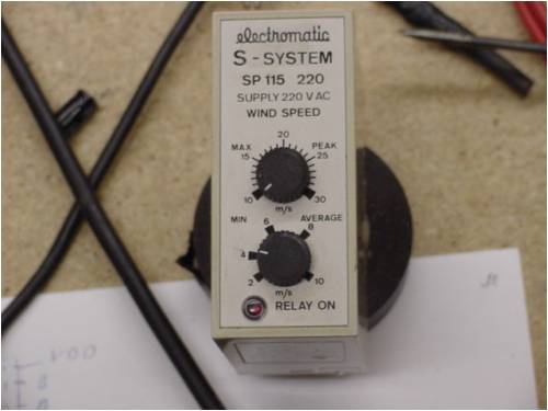
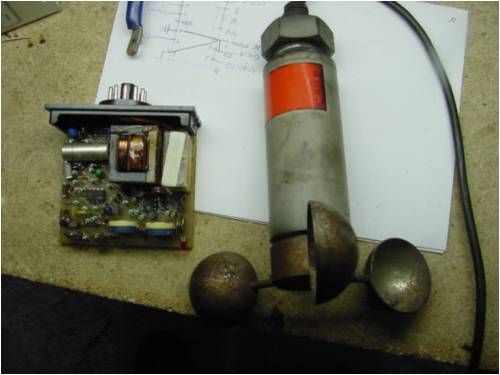
You asked to see the innards of one of the boxes I am fixing for the mills over here, and how I fixed it. I don't quite know what you want so here goes.
This 115 unit controls when to let the blades rotate. If there is not enough wind, it keeps the brakes on, When an average (settable from the front bottom control) wind has been established, it releases it's relay to let the brakes off.
Providing no other unit disagrees (phase drop, voltage wrong, vibration etc etc, the blades start to turn. It monitors this as an average all the time, if it slips below the preset (as an average taken over about 20 seconds (ish), it puts the brakes on and waits.
The top dial sets the upper limit you will allow the blades to run in. If it exceeds this it stops immediately.
This one won't come on.... so we open it up to find out whats inside.
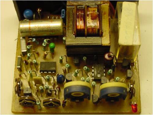
Note, the rotten #@#@(explicative deleted) ground the numbers off the two IC's... this makes it a bit harder.
After struggling with how it might work, I figured out the two IC's were simply lm358's. Tracing out the circuit around the devices led me to this conclusion, so with this in mind, I tested accordingly.
found the two outputs generated by the anemometer, the peak and the average signals. They were generated by one of the IC's. It went through some buffer stages (transistors) and wound up at the other IC.
Knowing it was a lm358 by now, it was simple to find the preset voltages from the pots on the front panel, in the -in inputs of either op amp. One for average, one for peak. It simply beat one preset against the average signal, and one against the peak signal (against the peak preset). The average signal went to +in, the preset to the -in, but the out didn't change when I pushed the average signal up... dead 1/2 IC. So replaced that 358.
Now we had the signals OR ing to an 14541 programmable timer chip (under that big electro). It was getting the signal, but not resetting and counting down. This turned out to be a shot capacitor. Replaced it and she all works again.
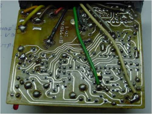
Here is the back of the board... at least you could see through it to trace the tracks to the component side:
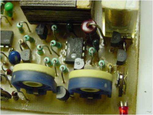
Here is the preset area:
Now, what made this harder than it should have been, (apart from those devious devils grinding the numbers off the IC's), was that I had to turn this while I was searching for the signal paths...
I reckon it would have been comical to see... spin... measure measure... spin.. measure measure.
In the finish I used the heat gun on cold air to spin the blades, and interrupt the airflow with my elbow to simulate change.... such is life for the free serviceman I guess.
Is that what you were after?
..........oztules
Village idiot...or... just another hack out of his depth
Dinges Senior Member Joined: 04/01/2008 Location: AlbaniaPosts: 510
Posted: 01:27pm 01 Dec 2008
Copy link to clipboard
Print this post
oztules Guru Joined: 26/07/2007 Location: AustraliaPosts: 1686
Posted: 07:44pm 01 Dec 2008
Copy link to clipboard
Print this post
Glad you enjoyed it. I only enjoyed it when I pushed it back inside it's case and tested it again... and it all worked properly.
No circuits for the mill, but there is one coming I'm told. It's a few thousand miles away at his other place.
The Chinese inverters I have had to work on lately all use phenolic (or something like that) board. You cant see through with the brightest light. It is no go. I am useless at imagining in mirror image too, which makes it difficult.
.........oztulesVillage idiot...or... just another hack out of his depth
Dinges Senior Member Joined: 04/01/2008 Location: AlbaniaPosts: 510
Posted: 08:13pm 01 Dec 2008
Copy link to clipboard
Print this post
Everyone needs to ask for help sometime. Your fellow islanders don't know half how lucky they are to have someone like you to help them with this kind of stuff. Tell them Peter said so.
Even if you can't... I bet they'll wait for you to solve their problem.
Now... if you could do small medical procedures and surgeries too... or would that be asking too much?...
oztules Guru Joined: 26/07/2007 Location: AustraliaPosts: 1686
Posted: 08:49pm 01 Dec 2008
Copy link to clipboard
Print this post
I can remove splinters and dispense aspro's. (although the guillotine could certainly do amputations...)
Does that qualify?Village idiot...or... just another hack out of his depth
GWatPE Senior Member Joined: 01/09/2006 Location: AustraliaPosts: 2127
Posted: 09:49pm 01 Dec 2008
Copy link to clipboard
Print this post
Hi oztules,
I am sure you could work out an arrangement with a ccd camera and a monitor to see both sides without turning things over.