Notice. New forum software under development. It's going to miss a few functions and look a bit ugly for a while, but I'm working on it full time now as the old forum was too unstable. Couple days, all good. If you notice any issues, please contact me.
Murphy's friend Guru Joined: 04/10/2019 Location: AustraliaPosts: 671
Posted: 09:33am 29 Sep 2021
Copy link to clipboard
Print this post
Quite some time ago warpspeed published a very clever saturation tester here which I built. It worked very well but it was cobbled together from some home etched PCB's and bits & pieces, not the easdiest kit to use.
So, having time on my hands I re did the PCB to fit the cheap 100x100mm Chinese boards.
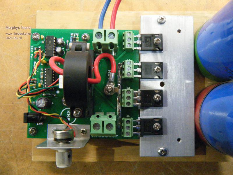
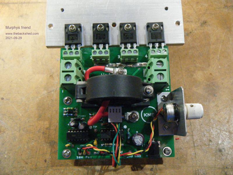
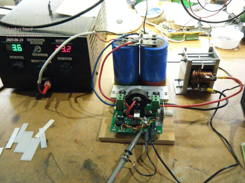
this is what it looks like:
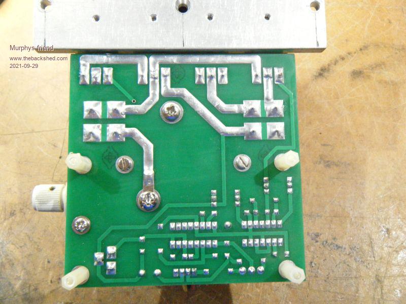
As this is only a 1 oz PCB I made provision to boost the power tracks with solder:
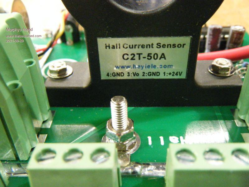
A HAll sensor is required, I used this one:
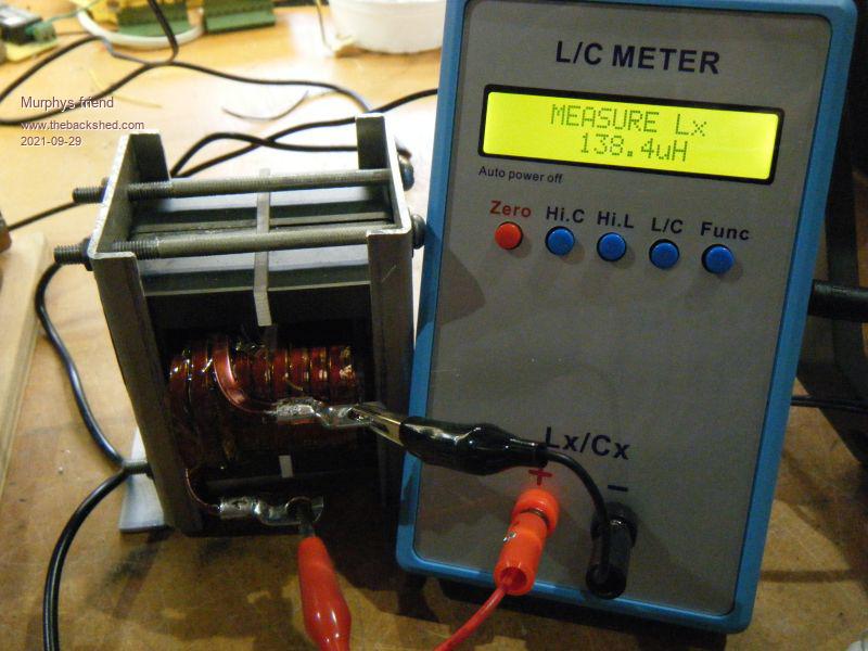
Here I am testing a choke for my (not yey finished) MPPT project:
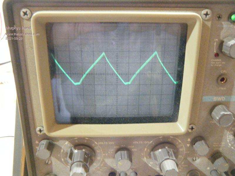
The wave form just before saturation (hand held camera ):
The power drawn from my power supply to get this wave form:
Details of the choke:
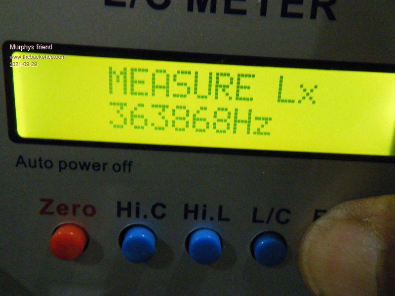
Measured at that frequency (not sure about that):
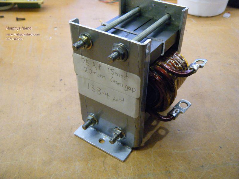
A close up of my choke. Its a dual E65 core with a 6mm gap. I gapped all 3 legs with 3mm perspex, doing it that way is a lot easier than grinding of the center leg. Its also much easier to change the gap to get the saturation point just right.
Lastly, another pic of the tester:
I have two spare PCB's here, if anybody wants them they can be yours for the price of postage (Australia only).
poida Guru Joined: 02/02/2017 Location: AustraliaPosts: 1432
Posted: 10:53pm 30 Sep 2021
Copy link to clipboard
Print this post
this all looks like fun.
What is the timebase setting in the CRO image? It appears the voltage applied to the inductor is 23.3V Also, what is the volts/div and current sensor gain (Amps/Volt)
From those answers we can determine the choke's inductance via Inductance = (Volts x Rise time )/ (Amps change during rise time)
You measured about 140uH so 140 uH = 23.3 x (rise time)/Amps Let's say Amps was (75/20) (from the label you put on the choke) or 3.75 Amps then I estimate the rise time of the current trace to be 23 uS And the vertical gain to be 1 Amp/div And the CRO time base to be 10uS/div
I like very much how well you built it too. wish I could do this
I found it very instructive to build a mppt board and run custom firmware that takes input from a pot to determine duty cycle width. Let the pot take it from 1% to 99%.
Then put a current sensor around the choke lead going to the MOSFETs and a suitable DC load on the output. With this setup I could test chokes under different input & output voltages and power levels. It became clear to me very quickly what choke was good enough and which ones would saturate. You could see it as you increased power via turning the pot.
But that is a ripper choke tester.wronger than a phone book full of wrong phone numbers
Warpspeed Guru Joined: 09/08/2007 Location: AustraliaPosts: 4406
Posted: 04:03am 01 Oct 2021
Copy link to clipboard
Print this post
Great effort there Klaus
In a way, a solar MPPT controller becomes its own choke tester, just monitor the current waveform with a Hall sensor and that will give a very good idea of what is happening.
Not really possible to do the same thing with an inverter though, as the choke current waveform is changing continuously throughout the 50 Hz sine wave. So the choke tester becomes a pretty important part of testing a suitable prospective choke for an inverter.Cheers, �Tony.
Murphy's friend Guru Joined: 04/10/2019 Location: AustraliaPosts: 671
Posted: 08:12am 01 Oct 2021
Copy link to clipboard
Print this post
Thanks Poida and yes, it was fun to build.
I can't remember looking at the CRO time base, I just adjust it to show a suitable number of peaks on the screen. Remember, the testers frequency can also be adjusted with that little pot on the right side.
That Hall sensor returns 40mv/Amp.
Your mind has an enviable capacity to crunch complex formulae, mine is more practical building oriented. So we look at a project from different angles.
I find it easier to use an inductance meter . I have that little one many others on this forum use as well but it refuses to switch from C to L now. That blue one shown above is a little more expensive but can measure much bigger L & C values.
If you would like a choke tester like this one I have a spare PCB, send me a PM and its yours.


 ):
):