
|
|
Forum Index : Electronics : SolarWorx Grid-Tied Inverter Conversion
| Author | Message | ||||
Revlac Guru Joined: 31/12/2016 Location: AustraliaPosts: 1282 |
Conversion....Might be a bold statement.....see how it turns out.  Its been a while, since Bruce asked if I could take a look at this to see what the possibilities are for converting these GTI's to a standalone off grid inverter. This one is a 24v model, the other is the TriSolar,48v version, mostly the same thing inside. Have connected this to some solar panels and it wakes up ok, nothing wrong, its a slave so it just waiting for grid voltage or connection to a combi system (Master) to add on to the combi offgrid inverter. It has a panel input voltage between 33-64V with a maximum of 80v according to the SolarWorx Grid-Tied Inverter Manuel. 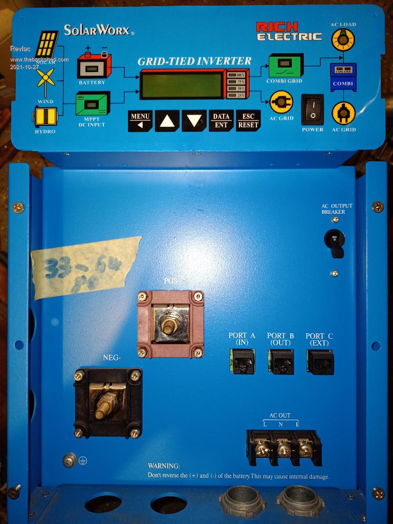 Part of the main power board, there was a 240v fan blowing into this.......There's a lot of fluff. 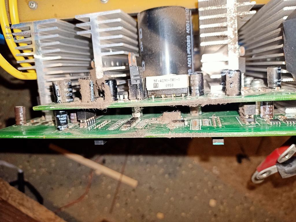 After a clean, we can see something, the whole unite looks very well build. 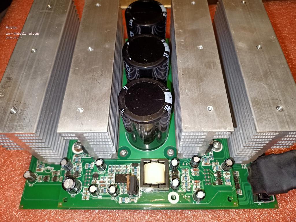 More details on this later. This is the transformer inside, can see the choke is mounted top center of the toroid, this is the 2kw model, and will need to be wound to suit 48v. First of all I will connect the transformer to a 240Vac power source and do a few voltage checks and see what sort of idel current we have to deal with, might get some time later this week. 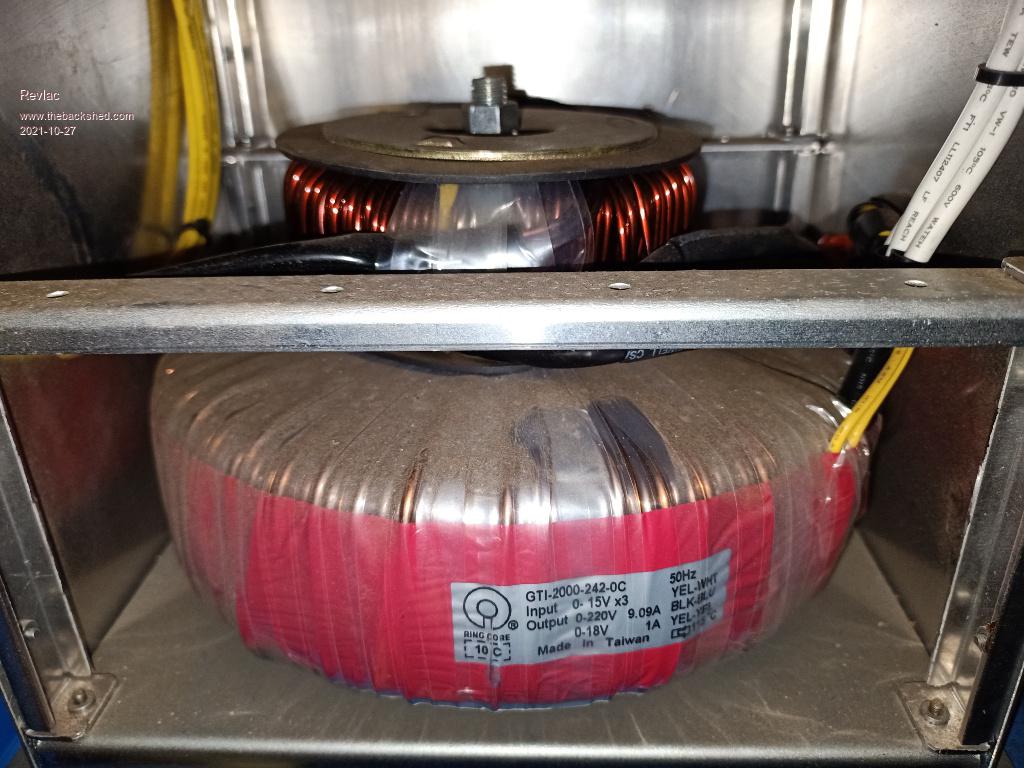 Cheers Aaron Off The Grid |
||||
| brucedownunder2 Guru Joined: 14/09/2005 Location: AustraliaPosts: 1548 |
Hi Aaron. Thanks for bringing this "Project" to the forum attention. I'll tell you all what I know from the friend that I got these(4) from. Nice guy ,used to sell batteries and solar installations. Had a connection with the distributor of these inverters, which were very popular and sold by jay car some time back. He told me that he thought there ws nothing wrong with a couple of them , the other two may have needed some work ?. Seemed like an honest type. So, he had to travel urgently,(family worries), so offered them to me as scrap.. Local guy ,and I sort of trusted him. Ok, so I was diagnosed with cancer and had to cease all my work and thats another story. I hope we can do something with these, as they are in near perfect condition(from my observation). Aaron has the "smarts" to trouble shoot , so I hope you can offer him some support in his efforts to bring these to a once-again useful life .. Thank you , Bruce Bushboy |
||||
| Revlac Guru Joined: 31/12/2016 Location: AustraliaPosts: 1282 |
It will take some time to figure this out, but I'm sure we will make something work.  Tested the Toroid today, 16.3v at the primary when tested @ 240Vac, the consumption was about 6 watts, not bad, some of that would be the meter, the size of the core would be a little smaller than others tested, so a few more turns could be added, not just to lower the consumption, but to get it further away from possible saturation. As it is now its not bad and could be used if some more primary turns are added to get up to 28v, that would be a nice backup inverter with idle consumption of about 18w The Toroid dimensions (With The Wire On) are 200mm wide 60mm high, the AC tuning cap is 1uf 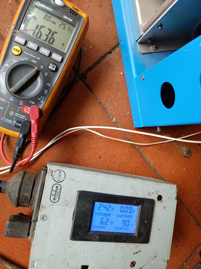 This half of the power board, the right hand side X1 connects to the toroid choke, the left side X2 is connected directly to the toroid primary, the center of the board is the negative supply. The reference designator's on some of the IC's have been sanded off and coated...VERY HELPFUL when those of us that might want find out what the IC's Actually are. Was able to read The chip on the other unit, it is R5F21114DFP a SINGLE-CHIP 16-BIT CMOS MICROCOMPUTER, with the correct commands it might possibly run the inverter, or it relies on the the master unit for that. 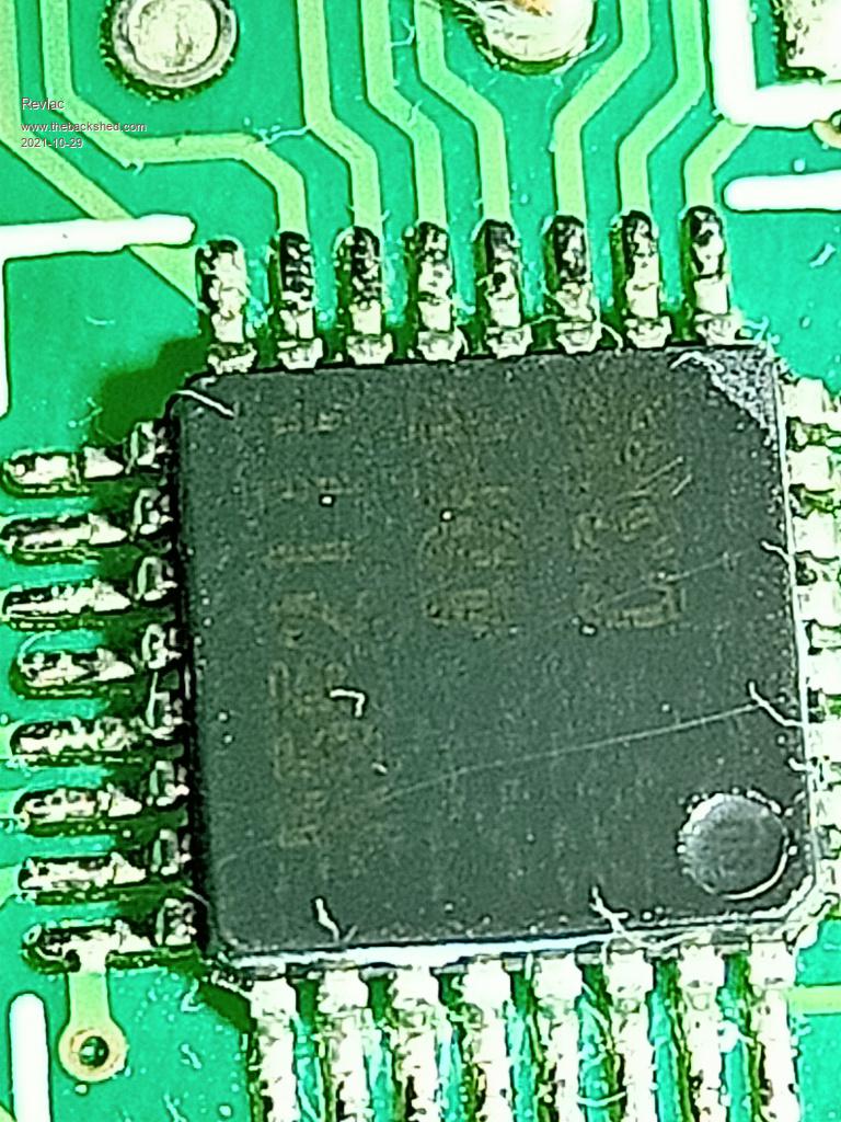 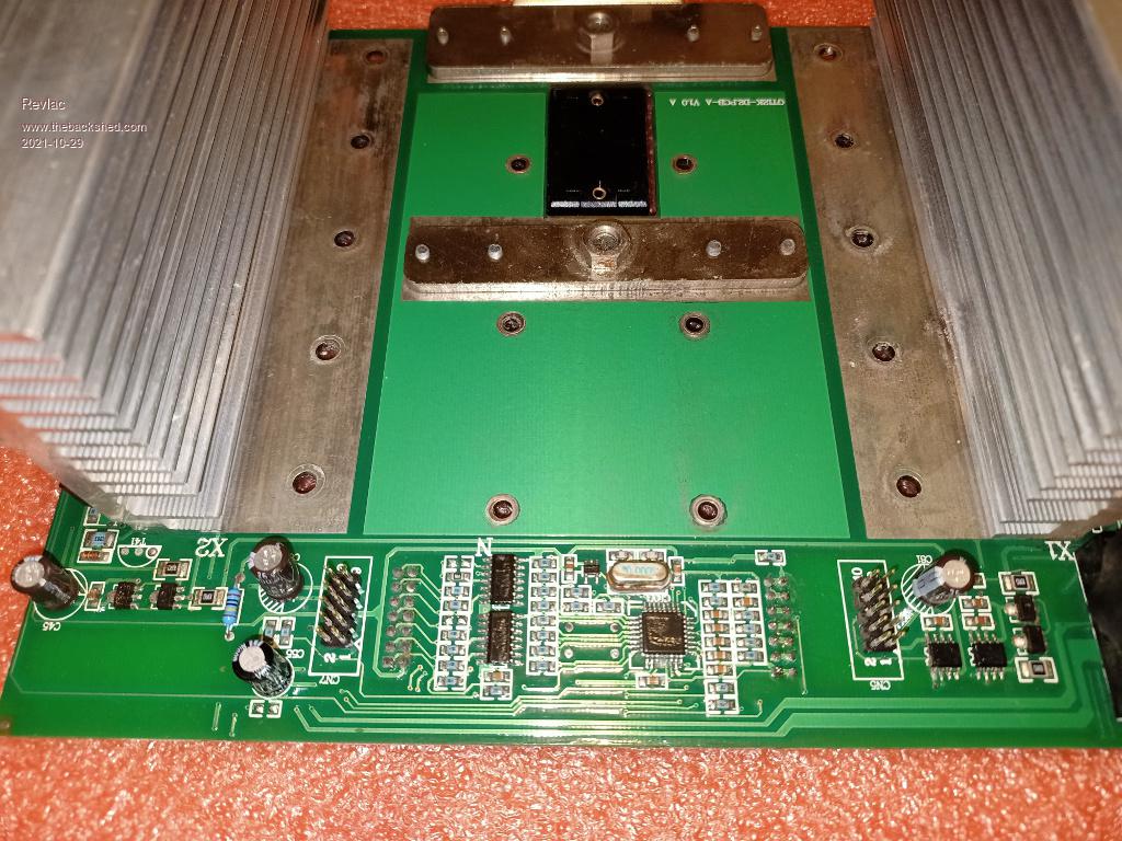 Mosfet drive, X2 side at first glance it looks all normal, nothing exciting, looking a little closer at the drivers they are marked MY (NPN) and NY (PNP), but there are 2 sets of them per side (leg) 1 set drives first 3 fets and the other set drives the other 3 fets most others I have seen have 1 set per H bridge leg, will have to trace this all through to see exactly whats what. NY 2SA1213-Y Type - PNP Collector-Emitter Voltage: -50 V Collector-Base Voltage: -50 V Emitter-Base Voltage: -5 V Collector Current: -2 A MY 2SC2873-Y Transistor Type - NPN Collector-Emitter Voltage: 50 V Collector-Base Voltage: 50 V Emitter-Base Voltage: 5 V Collector Current: 2 A 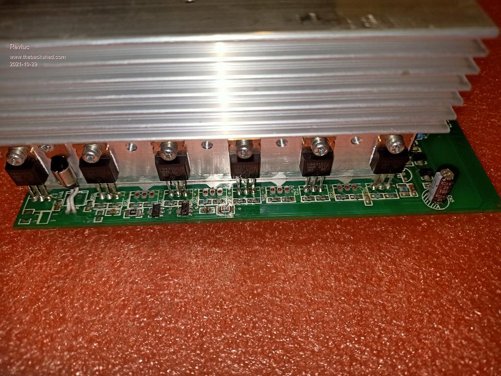 Options on the table so far: 1. Trick the cpu into running as an standalone inverter.......Beyond my knowledge at this time, might not be possible anyway. 2. open to interpretation? 3. use the picoverter to run the H bridge, if possible. Will have to sort out the drive with the 5 V Emitter-Base Voltage: or change it. 4. Make a new board and driver, then just use the Toroid and case, to make a backup inverter that way. Cheers Aaron Off The Grid |
||||
| Revlac Guru Joined: 31/12/2016 Location: AustraliaPosts: 1282 |
Going with Option 3. Had a go at tracing the circuit, and have worked out some of it. Looking at one leg of the Bridge, it uses 2 totem pole gate drives , one drives up to 5 fets the other drives the other 5 fets equally, so a total of 8 totem pole drivers over the entire bridge. Not 100% sure its drawn out correctly, and this is the first time I have drawn a schematic.......so if it looks like I stuffed it up...I probably have. There are a pair of (8 pin SMD) mosfet drivers NOT SHOWN, Don't have a clue what they are, so I just put the IR2111 there for displayed purposes. Gate drive Trisolar.pdf 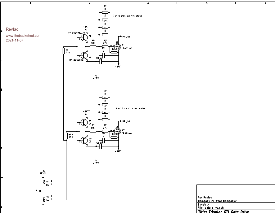 I think the easiest spot to connect a gate drive (wire from Picoverter pcb) would be at the SMD resistor above the X2 marked on the H Bridge pcb, then DITO. 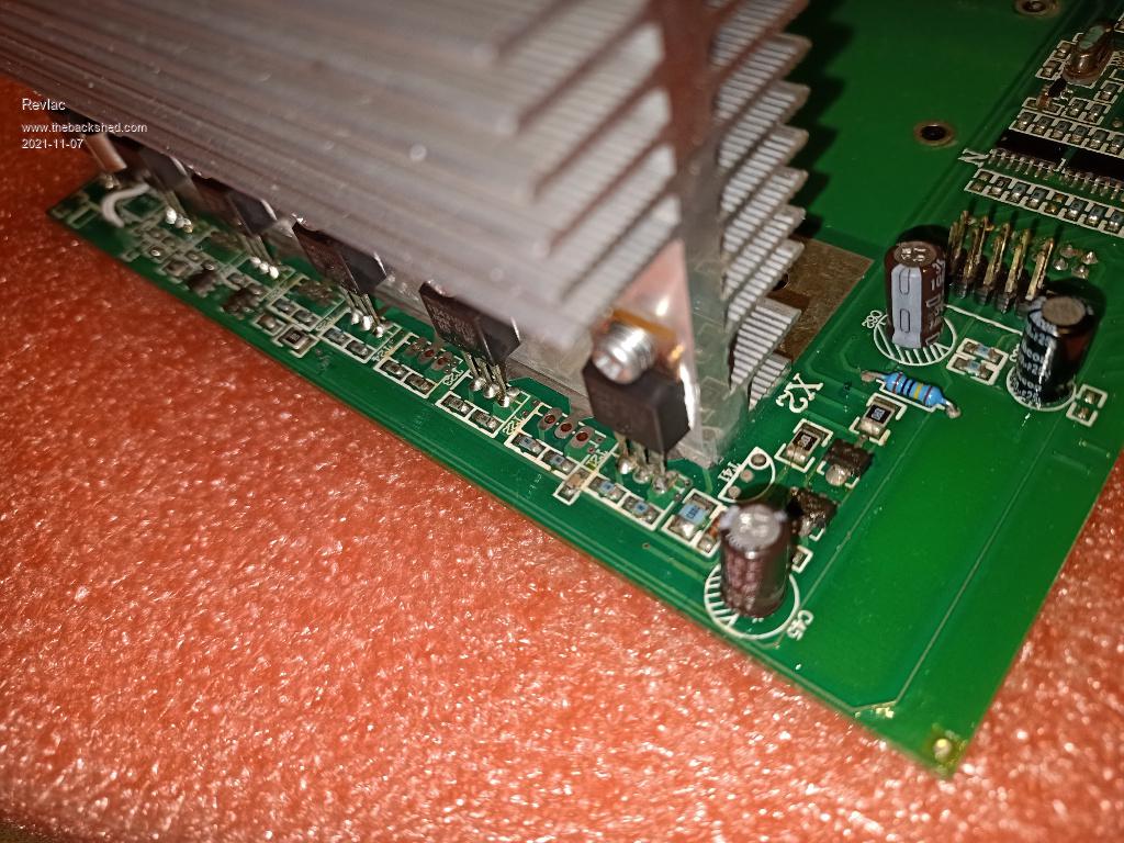 Still have to find the correct places for the other wire connections, then figure out the power supply. Cheers Aaron Off The Grid |
||||
| wiseguy Guru Joined: 21/06/2018 Location: AustraliaPosts: 1297 |
Good effort Aaron, the 2SA is actually a PNP - you drew it as an NPN and vice versa the 2SC is NPN not PNP. I think option 3 is a good choice too. The Gate resistors from the 2SA/2SC buffers seem a bit high - by my calculations with the values shown, the maximum Gate current with all 5 FETs driven is ~ 160mA each or ~ 800mA total. The buffers could easily drive double that. Edited 2021-11-09 01:06 by wiseguy If at first you dont succeed, I suggest you avoid sky diving.... Cheers Mike |
||||
| Revlac Guru Joined: 31/12/2016 Location: AustraliaPosts: 1282 |
Thanks for checking Mike, I had an idea something was wrong there, Didn't see any of these transistor's in the Kicad library, so I edited that and stuffed it up, will have another go at it later when I get time. Yes, gate resistors do seem a bit high, I will check the other inverter later, it could be a different value. Cheers Aaron Off The Grid |
||||
| The Back Shed's forum code is written, and hosted, in Australia. | © JAQ Software 2026 |
