
|
|
Forum Index : Electronics : PCB design to my door in 6 days
| Author | Message | ||||
| poida Guru Joined: 02/02/2017 Location: AustraliaPosts: 1387 |
I have a need for a sort of dumb, slow is OK, close enough is good enough power supply that can do 10 or 15 Amps at up to 100V 55V at 10-15 Amps for inverter testing 100V at 10 Amps for mppt testing 54.6V for ebike battery charging at 5A or 10A or even at 1C which would be 20A I based it on the mppt but only need 1 FET and one diode. It incorporates the Hall type current sensor short circuit protection I have just developed. Runs on a Nano (of course) which lets me make it more than a charger or simple PS. It can do constant power if I want (mppt testing...) Only bits I needed to buy were the Allegro current sensors. 6 days from uploading to jclpcb to having the result in my hand. It looks like this. 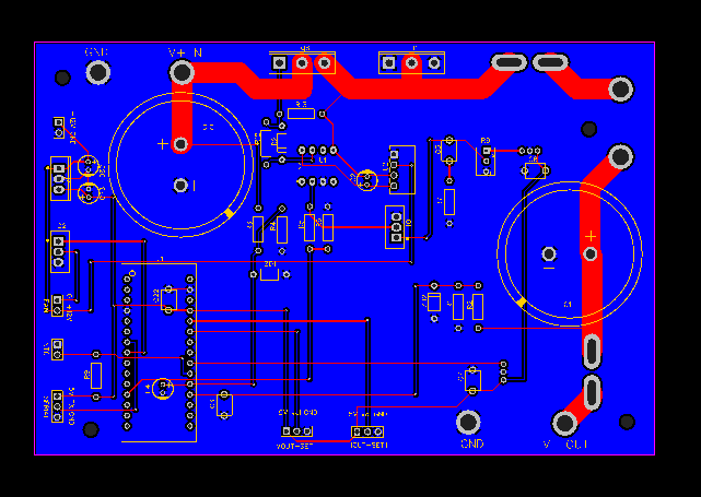 the actual pcb is: 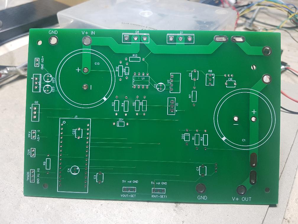 the result will be: 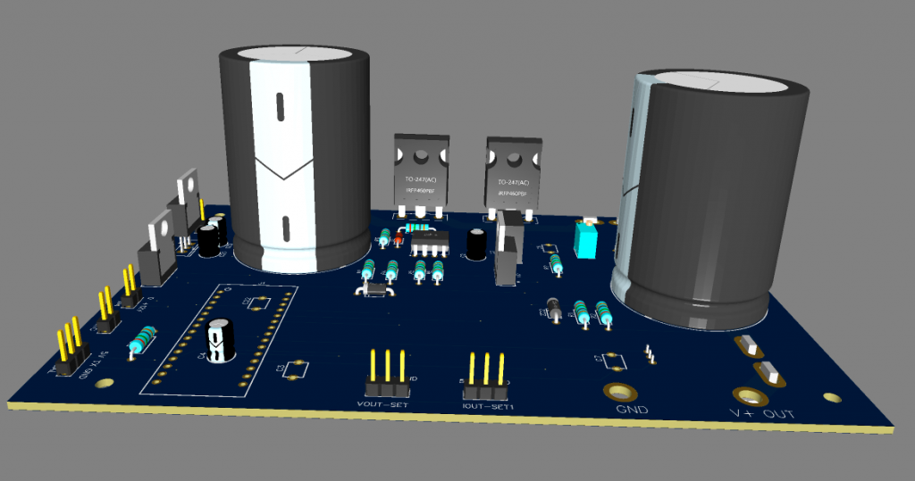 the schemeo: Schematic_dc-dc supply_2021-10-28.pdf It's not really special or warranting a post here. I just wanted to tell someone that I find it astonishing to have a pcb for my power supply within 6 days. No hassles. Just $38 for 5. This is cheap and good quality and fast. This completely nukes any idea of home brew pcb production. The PS will have a 20x4 LCD showing Vin cc/cv Vout Iout Vset Iset Watts Amp.hrs The setting will be from 2 single turn pots. Output voltage is not important and when charging the LiPo ebike battery I willset it at 54.0V to allow for a little inaccuracy in the design. DC supply comes from the left over toroid out of the dead Victron inverter plus a diode bridge. Put a few secondaries in series and I get 100V at 10A Cooling will be a ex-PC cpu cooler with fan module. This will be driven by the nano and a 10K NTC thermistor. All the usual stuff. But I have wanted a bigger PS for ages. And thought why not just make it? Edited 2021-10-28 17:31 by poida wronger than a phone book full of wrong phone numbers |
||||
| Warpspeed Guru Joined: 09/08/2007 Location: AustraliaPosts: 4406 |
Glad to hear JCL are still in business, I was wondering about that. Big problems in China with floods, power disruptions, and huge discontinuities in the financial system about to fracture mostly caused by a trade war with Australia. A week or so ago, China sent a nuclear capable ICBM over Sydney, and our navy is now in the Taiwan strait. We certainly live in interesting times (from an ancient Chinese curse). Cheers, ĀTony. |
||||
| Clockmanfr Guru Joined: 23/10/2015 Location: FrancePosts: 427 |
My large A4 size PCB's with double copper thickness double sided Power Boards are arriving today, 28th October. They were shipped, according to the Chinese company i use, shenzhen2u, on the 19th of this month. Shipped with DHL, to my French house, but because EEC Europe are now implementing all customs checks and VAT charges, a 180gbp order now has another 36 and the standard DHL paper work charge of 40. So another 76gbp for me to pay the DHL company, its getting crazy here, anything made in China is getting very expensive. Everything is possible, just give me time. 3 HughP's 3.7m Wind T's (14 years). 5kW PV on 3 Trackers, (10 yrs). 21kW PV AC coupled SH GTI's. OzInverter created Grid. 1300ah 48v. |
||||
| poida Guru Joined: 02/02/2017 Location: AustraliaPosts: 1387 |
It works. about 95% conversion efficiency (+/- a couple, likely minus) 30.3V 2.63A in 12.7V 6 A out The heatsink still cold as after 20 minutes All I need. Of course the conversion efficiency will drop a lot when I feed it 100V and draw 12V output. I am thinking of switching the various secondary winding's into the input as the set point voltage changes. This to keep Vin a bit more than Vout and so conversion efficiency very high. 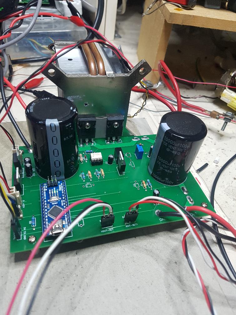 wronger than a phone book full of wrong phone numbers |
||||
| Warpspeed Guru Joined: 09/08/2007 Location: AustraliaPosts: 4406 |
I use a 1:1 mains isolation transformer, a variac, a bridge rectifier, plus an appropriate electrolytic to do something like that. 0 to over 300v dc at 10 amps. A bit rough and ready, but for something a bit experimental it can be put together very quickly and does the job. Cheers, ĀTony. |
||||
| poida Guru Joined: 02/02/2017 Location: AustraliaPosts: 1387 |
If I had a variac on hand I would have done the same thing and not the above. And added a motor to drive it with closed loop control wronger than a phone book full of wrong phone numbers |
||||
| Murphy's friend Guru Joined: 04/10/2019 Location: AustraliaPosts: 581 |
You must have a decent size variac there Tony, mine is only 500W  |
||||
| Warpspeed Guru Joined: 09/08/2007 Location: AustraliaPosts: 4406 |
I have one of those too, kind of like an oversized potentiometer. Then I have my ten amp one which is the most useful. But also lurking on my bench is a three phase fifteen amp variac with motor drive. Hardly ever use it though, its pretty enormous. Cheers, ĀTony. |
||||
