
|
|
Forum Index : Electronics : Evaluate This Circuit
| Author | Message | ||||
| InPhase Senior Member Joined: 15/12/2020 Location: United StatesPosts: 178 |
This would be 1/4 of an H-bridge intended for inverter use. My thought is to use multiples of this if need be for more current. I understand that using the TLP350 as well as the totem pole is a little wasteful, but I want it to be bulletproof. Please give me your thoughts and criticism. 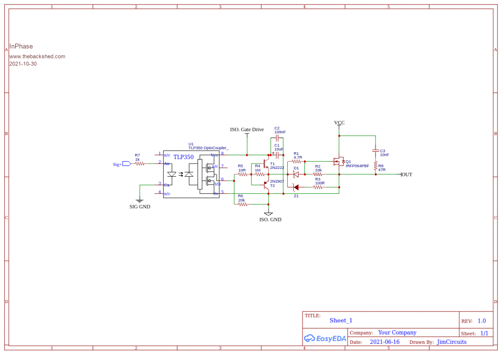 |
||||
| Warpspeed Guru Joined: 09/08/2007 Location: AustraliaPosts: 4406 |
TLP350 all by itself will deliver far more peak drive current (two amps) than the two bipolar transistors are capable of. Just connect pin 6 straight to D1 and eiminate T1, T2, R4, R5, and R6. Cheers, �Tony. |
||||
| InPhase Senior Member Joined: 15/12/2020 Location: United StatesPosts: 178 |
Gotcha! I was trying to add a layer of robustness to the circuit, despite the lower current capacity of the transistors. Hoping that if the FET dies it will take the 2 transistors out instead of the $5 driver chip. If that is just day dreaming, I'll nix it. |
||||
| Solar Mike Guru Joined: 08/02/2015 Location: New ZealandPosts: 1162 |
The TLP350 is an older device more suited to driving IGBT's, ie its slow and has a large variation propagation and switching delay between devices. For an inverter H-Bridge driver using mosfets I wouldn't use it, as these variations may stuff up any dead time settings from your PWM drive circuits. A modern equivalent better device would be the Si8261 series of gate drivers Link Here, another suitable alternative would be the UCC23313. If paralleling of mosfets are required you can use a low current isolated driver and totem pole transistor buffers, those low current devices in your circuit whilst fast enough, don't have enough current capability to switch your mosfets quickly; something like 2SC5707-TL-E // 2SA2040-TL-E would work here. Cheers Mike |
||||
| InPhase Senior Member Joined: 15/12/2020 Location: United StatesPosts: 178 |
Well darn. That drive is nice, and the price at Mouser is good too. I have a whole sleeve of TLP350s though. I'll have to call back and punt I guess! |
||||
| Solar Mike Guru Joined: 08/02/2015 Location: New ZealandPosts: 1162 |
Seeing as you already have a bunch of those TLP350's, would be a shame to chuck them out, you could try them, but checking the pwm timings on all 4 bridge circuits to make sure dead time etc is not being compromised, prior to turning on the power to main mosfets. Pinouts are similar to the Si8261 series, so pcb layout would be the same. The suggested 2SC5707//2SA2040 totem pole drivers would drive up to 4 parallel mosfets gates ok, using a 3.0R gate resistor with 12v drive power. A lot of the newer gate drivers are out of stock, even the manufactures web stores mostly have none!! so design compromises may have to be used. Cheers Mike |
||||
| wiseguy Guru Joined: 21/06/2018 Location: AustraliaPosts: 1206 |
I would reduce R4 to ~ 200R any current over a few milliamps will shunt current into the bases of the buffer transistors allowing them to buffer as desired, as an added bonus the final gate voltage will quickly be held the same as the opto's output (no Vbe drop from the buffers). Omit R3 and put the zener directly to ground - I assume a zener of ~ 16V. The zener position has a few compromises, if protecting the FET from gate over voltage put the zener between the gate and source directly. If protecting the upstream parts such as opto etc if the FET dies and goes feral the zener is fine where you have it but the 100R resistor will probably instantly fry and go open circuit to protect the zener but may still kill all the upstream bits. Better to have a dead zener and all upstream bits have a better chance of survival so make R3 zero ohms. Make sure R7 is low enough to meet a few milliamps above the minimum recommended LED current taking into account the forward voltage drop of the lED in the opto and the drivers output voltage at the drive current. Other than that & the other advice its good to go. Edited 2021-10-30 19:45 by wiseguy If at first you dont succeed, I suggest you avoid sky diving.... Cheers Mike |
||||
| InPhase Senior Member Joined: 15/12/2020 Location: United StatesPosts: 178 |
Great feedback guys! I've modified the circuit to reflect the suggestions here. I plan to use a TLP350 per FET, so I've eliminated the transistor buffer altogether as Tony suggested. I've changed from an RC snubber to a schottky diode. is there any reason to prefer one over the other? Should I use both? 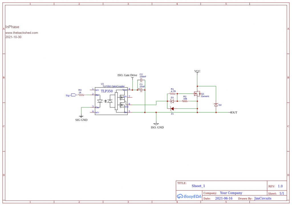 Edited 2021-10-30 23:41 by InPhase |
||||
| The Back Shed's forum code is written, and hosted, in Australia. | © JAQ Software 2025 |
