Notice. New forum software under development. It's going to miss a few functions and look a bit ugly for a while, but I'm working on it full time now as the old forum was too unstable. Couple days, all good. If you notice any issues, please contact me.
stockleys Regular Member Joined: 21/06/2019 Location: United KingdomPosts: 54
Posted: 09:13pm 17 Mar 2022
Copy link to clipboard
Print this post
hi all
its beena while since i last posted on here.
i am looking to build a low frequency inverter 24v 3kw 230v.
i already have the aerosharp 3kw transformer and re wound it for 13v,
i have a board coming from aliexpress.
now the inductor recomended for the board is 47uh, but the diagram on the listing shows 48v, also, i cant seam to find an inductor of 47uh.
i have found one that says its for 24v 3kw but is 25uh or a 48v 3kw at 45uh,
which size would you recomend i get?
many thanks in advance
Godoh Guru Joined: 26/09/2020 Location: AustraliaPosts: 675
Posted: 01:20am 18 Mar 2022
Copy link to clipboard
Print this post
Inductane doesn't have much to do with voltage from what i know. I have a couple of inverters that are 24 volt and 3kw. I used a 65mm E core ferrite inductor core and wound 4 turns of heavy cable through it. Not totally scientific but they inverters work well and don't draw much idle current. Unfortunately the man to ask no longer comes to the site. If you are getting a chinese 8010 based board there are a couple of modifications that help make them blow up proof. I am not sure where they are on the site but they involve stopping the over current circuit from working. The boards have two different overcurrent protection circuits that can fight each other and cause them to blow up. The easiest way I know of is to bend pin 1 of the 8010 board out so it does not make a connection at all. Otherwise there are a couple of resistors and a small chip (LM393 I think) to remove. Hopefully someone more knowledgeable will let you know more. Pete
Revlac Guru Joined: 31/12/2016 Location: AustraliaPosts: 1282
Posted: 01:58am 18 Mar 2022
Copy link to clipboard
Print this post
stockleys, If you have the spare time to dig around through the forum you can find several examples about making your own choke with aerosharp choke cores, if you have an inductance tester on hand it will make the job a lot Easier learning experience and be happy with the DIY result.
It has been said that more is better, but better to have some than none at all, Also check the current rating on the advertised chokes, see if they are up to the task.Cheers Aaron Off The Grid
noneyabussiness Guru Joined: 31/07/2017 Location: AustraliaPosts: 527
Posted: 06:26am 18 Mar 2022
Copy link to clipboard
Print this post
don't touch the eg8010's pins, oztules rigorously tested it and it works fantastic... you will need to jump pins 7 to 8 and 1 to 4 on the 393 op amp.. also put a 18v tvs diode on the gates of the mosfets, at least 1 on each " bank " of mosfets..
as for the inductor, at least 3 turns on a ferrite toroidal core is sufficient, if warp was around he could talk you through a " proper " one..
as has been stated, there is plenty of info if you search up setting these boards up, once set up they are almost indestructible...I think it works !!
nickskethisniks Guru Joined: 17/10/2017 Location: BelgiumPosts: 481
Posted: 09:59am 26 Mar 2022
Copy link to clipboard
Print this post
The best advice I got in the past was something like this:
Use the biggest core you can find/afford and put on as many turns you can, make sure you use wire that can carry the current. After this you can adjust the airgap until you reach your desired inductance.
I think many of us used around 50uH as a good value, more is possible and some did. But in my case, the higher I went the more the waveform was disformed. If you want to take it to perfection you will want to have a high enough saturation point of the inductor, that way the inductor keeps it's inductance value during operation.
tinyt Guru Joined: 12/11/2017 Location: United StatesPosts: 561
Posted: 08:55pm 29 Mar 2022
Copy link to clipboard
Print this post
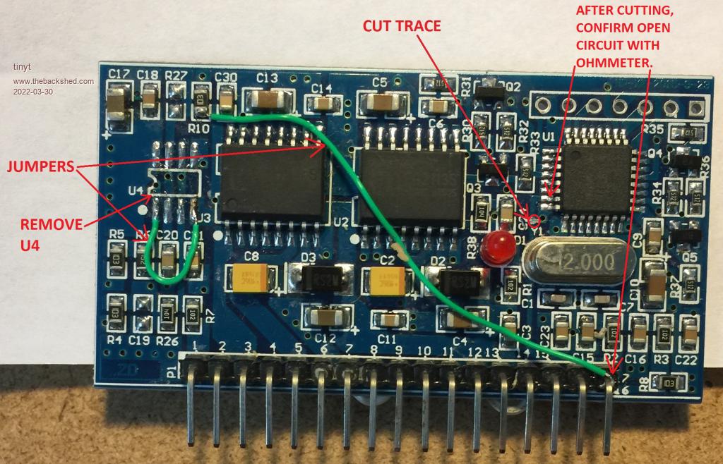
Dug up picture of my EGS002 mod.
noneyabussiness Guru Joined: 31/07/2017 Location: AustraliaPosts: 527
Posted: 05:23am 30 Mar 2022
Copy link to clipboard
Print this post
seems unnecessarily difficult.. seriously, jumping pins 1 to 4 and 7 to 8 on " U4 " will do the same thing... but in addition, the original " instant " current control of the eg8010 will continue to work if need be... why we had to remove the lm393 in the first place, it would " fight " the eg's current control and you would cause spurious drive signal to mosfets causing instantaneous combustion..I think it works !!