
|
|
Forum Index : Electronics : Automated Discharger for Large Batteries
| Author | Message | ||||
| Solar Mike Guru Joined: 08/02/2015 Location: New ZealandPosts: 1228 |
I'm looking for something to discharge Lifepo4 battery cells at a constant current down to a predefined cell cut-off voltage. I don't need to measure power out, just bring them down to a fixed value. I have been using a CellPro PowerLab 8, for smaller batteries, but its pretty hopeless on these larger 400 AH battery cells and I have a lot to do. Spec is discharge individually at 30-50 amps down to a set 2.9v, then taper off discharge current to approx an amp @2.9v; at that point cell is virtually fully discharged. If anyone has seen something to do this, please post a link. Cheers Mike |
||||
| Godoh Guru Joined: 26/09/2020 Location: AustraliaPosts: 675 |
Hi Mike, I don't know if it would work for your situation but I use a Victron BMV712 on my solar setup. It has a relay built in that allows it to switch loads on and off at user defined set points. I use the relay on mine to control my hot water system. When the batteries are fully charged and there is not enough heat in the sun for the evacuated tubes to heat the water I turn on the electric element. I have mine set so that it only uses the top 3% of the battery charge, that way I am basically only using solar power to heat the water and not taking the batteries down too much. If you used a few elements in a water tank it could be a way for you to do what you want. Pete |
||||
Revlac Guru Joined: 31/12/2016 Location: AustraliaPosts: 1282 |
ET5410 Not sure if it will do what you want and might be too slow towards the lower voltage, not cheap either. Just thinking how it could be done, how about a set of load resistors of appropriate sizes, a micro controller with its own power supply, first it will switch on a large relay with a load resistor that will dump 50Amp, a voltage sensor can trigger the controller to switch off that relay at 2.9v and onto the next relay load resistor that will dump about 20Amp or less, when that reaches 2.9v it will then trigger the controller to go to the next and so on, the last trigger will switch off permanently. Its just a thought And probably missed all the difficult stuff in between. Or I'm too far off the track,  Cheers Aaron Off The Grid |
||||
| noneyabussiness Guru Joined: 31/07/2017 Location: AustraliaPosts: 527 |
where's Poida when you need him... pwm into a large resistor or a bank of 24v 250watt light bulbs , controlled with a arduino on a sliding scale would be perfect for you... I think it works !! |
||||
| Solar Mike Guru Joined: 08/02/2015 Location: New ZealandPosts: 1228 |
All good ideas; I like the "ET5410", will have to read its manual to see if CC mode will discharge at a constant 40A down to a set voltage, may not do that, from past experience, when they spec 40A they mean 40A for a few seconds and generally use at 80% of the rating, except for 24hr operation then its 50% of rating. Switched load resistors seems a more robust method, would use mosfets to do the switching, simple picaxe or similar would handle that, using a multi-turn pot to set the cut-off reference. Big bank of light bulbs coupled with PWM, this would still have 40A pulses averaged over time, I want the pulses to lower in peak value at my cut-off point, so that method will only work if a series inductor is used to reduce the current ripple peaks, bit like a buck regulator with a fixed resistive load. In past 2 days have managed to flatten just one 800Ah 3.3v cell, its going to take over a month to do this manually. Cheers Mike |
||||
| Solar Mike Guru Joined: 08/02/2015 Location: New ZealandPosts: 1228 |
Think I might make something using a simple buck converter, to load up the battery under test with any current between 0 and 50 amps, set by a 10 turn panel mounted pot. Same for the battery voltage end set point, use a similar pot to present a reference voltage to the cpu; cpu will have a 4-wire differential voltage sense connection to the battery terminals to exclude voltage drops in the high current wires. Something like this, block dia. 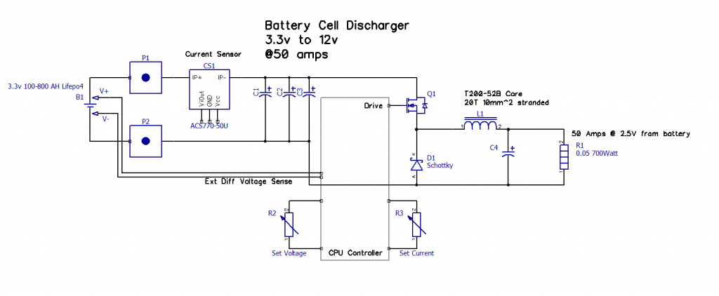 Building it this way allows connection to different battery cells without having to alter the load resistor too much. The cpu can lower the current as the battery gets down to its end point. I will get 7 of those 100W 0.33R aluminum shell resistors and place them in parallel bolted to a sheet of alloy with a small fan. About to send some pcbs away, so will make up a design for this in the next week or so. Cheers Mike |
||||
| nickskethisniks Guru Joined: 17/10/2017 Location: BelgiumPosts: 481 |
Something similar like I do, did you also consider the boost converter topology? Electricity is very precious for me in winter so I made a small boost converter, also because my Chinese module died and I wanted something stronger. This way I can test batteries on an efficient way, I just connect for example a 12V battery to the boost converter and dump all it's energy in the 48V main battery. The pwm is created by a TL494 wich can be shut off by the bms or something else. In my case it limits the input current and the output voltage. I did try it on 3,2V lifepo4 cells too and was amazed by the current handling, 40A input with TO247 components no problem, wires need to be thick and short or it's limiting the current just by wire resistance alone. Something to think about. |
||||
| The Back Shed's forum code is written, and hosted, in Australia. | © JAQ Software 2026 |
