Notice. New forum software under development. It's going to miss a few functions and look a bit ugly for a while, but I'm working on it full time now as the old forum was too unstable. Couple days, all good. If you notice any issues, please contact me.
Haxby Guru Joined: 07/07/2008 Location: AustraliaPosts: 418
Posted: 11:44pm 16 Apr 2022
Copy link to clipboard
Print this post
Morning gents.
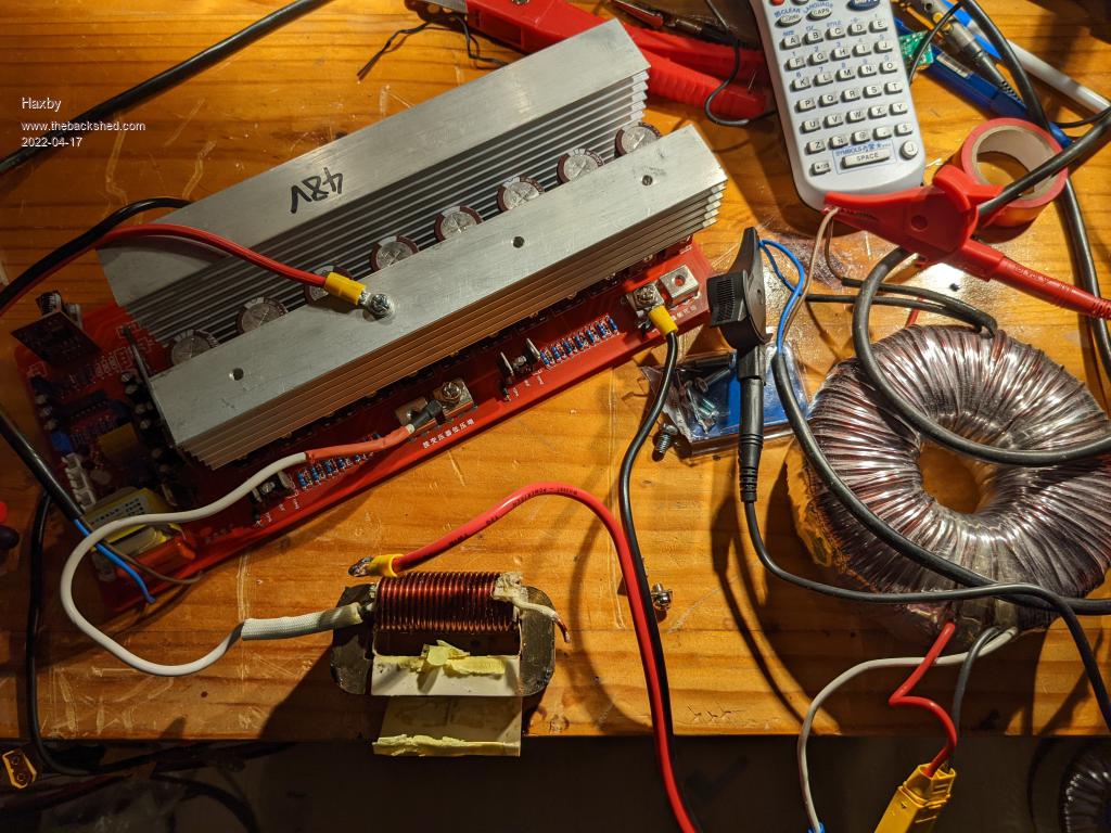
I'm building an inverter with very low self consumption for camping and RV use. This will use one of those sunyima inverter boards for SPWM.
The batteries will be reclaimed laptop 18650 lithium ion in a 10 parallel, 14 series arrangement. So approx 42v when discharged and 56v when charged.
So at 42v, the primary winding of the transformer should be 30v=42/?2
Now it just so happens that I have a 43v transformer on hand. So I'll have to either unwind some of the primary to get to 30v OR add to the 240v side.
The idea of adding windings to the 240v side appeals, as the transformer will become more efficient due to lower flux density. But I think winding the windings will be tricky.
I estimate I'll need 2 turns per volt, so I'll need to add about 120 turns to the original 240v side.
Now the hole is only 30mm diameter to start with and the online calculator says I can fit 213 strands of 1.8mm wire through it. Sounds good!
But... In the real world, how would I go about trying to wind this wire through an ever decreasing hole size.
I love the hoop idea, but that in itself will be 15mm diameter as a minimum. And as I'm starting with a 30mm hole, I don't think it's the solution.... I wonder if anyone can think of an even smaller hoop material, or any other ideas.
phil99 Guru Joined: 11/02/2018 Location: AustraliaPosts: 1769
Posted: 12:41am 17 Apr 2022
Copy link to clipboard
Print this post
Perhaps it might be best to leave adding the extra turns till after you have it running. Test all the things you plan to take on your travels on it and see if the lower voltage matters. These days most products are designed for global markets and are very flexible about supply voltage.
Haxby Guru Joined: 07/07/2008 Location: AustraliaPosts: 418
Posted: 01:06am 17 Apr 2022
Copy link to clipboard
Print this post
I have tested it as pictured without modifications. At 47v supply voltage the sine wave was beautiful with the choke pictured. And self consumption was under 5W for the whole thing. The switching circuitry was responsible for most of that figure. Fantastic.
But the output voltage was 180v, which is in line with the calculations. So not just the voltage but also the total power output will be marginal.
By winding the extra turns on the secondary, I can get another 25% of power out of the transformer with NO practical extra increase in self consumption.
I appreciate that most devices will run just fine on this voltage, but it would be good to get more out of it for the cost of some elbow grease.
rogerdw Guru Joined: 22/10/2019 Location: AustraliaPosts: 792
Posted: 02:57am 17 Apr 2022
Copy link to clipboard
Print this post
Mmmm ... sounds like a great project. What size wire are you planning on using?
It may be a slower process ... but if you wind a large diameter loop (say 1mtr diameter, maybe bigger) through the centre but without a hoop ... and if you tie it together somehow, it can be self supporting.
Of course the frustrating part will be freeing up another turn each time you need more wire ... so the binding process for the loop needs some ingenuity.
What if you used a number of short lengths of fairly stiff tubing just big enough to contain the wire (spaced out around the loop) ... and put a split in them, to pull out the wire when needed.
The hard part is that you'll probably need two hands to free up a loop each time ... so you can't keep tension on the wire with your hand and will need another method to keep it from coming loose on the toroid.
I have a large spring loaded plastic clamp that does a great job of holding either the wire or the mylar tape whenever I need to let go. One of them could be handy in this case.Cheers, Roger
Haxby Guru Joined: 07/07/2008 Location: AustraliaPosts: 418
Posted: 05:32am 17 Apr 2022
Copy link to clipboard
Print this post
"Fairly stiff tubing" yes I'm thinking the same thing but I can't picture what sort of tubing to use. It would have to be quite thin so as not to use up too much of the hole.
Haxby Guru Joined: 07/07/2008 Location: AustraliaPosts: 418
Posted: 06:11am 17 Apr 2022
Copy link to clipboard
Print this post
Oh and to answer your question, I was going to use the 1.8mm (or is it 1.7mm) aerosharp wire. I don't need the current handling but I've just got it sitting here.
Murphy's friend Guru Joined: 04/10/2019 Location: AustraliaPosts: 580
Posted: 07:01am 17 Apr 2022
Copy link to clipboard
Print this post
Use just ordinary short pieces of 13mm poly pipe. There is no need to split them. Thread the wire through each in turn as you form your self supporting hoop. Try to avoid cross overs. 1.8mm wire should be stiff enough to self support if the 'hoop' is not too large. Actually, after you formed your initial 'hoop' through the toroidal hole and you see you have a lot of wire 'wiggle' room left in that hole you can always make that 'hoop' smaller by pulling more turns through the poly pipe pieces. That was the hard part.
Now the easy part, just shuffle those poly pieces along the 'hoop' as you use up wire from it. There is no need for those pieces of poly pipe to pass through the hole. You will find each poly piece falling off as it finally runs out of wire through it.
Happy winding.
Haxby Guru Joined: 07/07/2008 Location: AustraliaPosts: 418
Posted: 07:14am 17 Apr 2022
Copy link to clipboard
Print this post
Aha that's a good idea. Have you done this before? Any particular diameter to aim for?
Murphy's friend Guru Joined: 04/10/2019 Location: AustraliaPosts: 580
Posted: 10:02am 17 Apr 2022
Copy link to clipboard
Print this post
The primaries of my warp inverter were wound with the 'wire hoop' method. Diameter is governed by wire length (bigger dia., less loop turns) and what you find convenient to work with.
Form a convenient size loop and slide the poly pipe pieces over the wire end. Keep feeding them round and round, making sure the wire end enters each piece at each turn, until all the wires are trapped.
rogerdw Guru Joined: 22/10/2019 Location: AustraliaPosts: 792
Posted: 03:16pm 17 Apr 2022
Copy link to clipboard
Print this post
Hi Phil, the tubing I use is from a child's hoop 680mm diameter and tubing 18mm diameter, though has a slightly bigger sleeve for the join.
It is nice and self supporting.
It holds 2.1 metres per loop and will hold 60 or 70 metres total, though I've only ever loaded up to about 54 metres at most.
I'm not sure what other smaller tube would be comparative �... �maybe some air hose type tubing �... �the stiff clear plastic type used for air cylinders etc or something like that if they make it big enough to be useful.
With enough loops of copper wire inside, you'd get away with plastic insulation sleeving �... �but once you get down to just a few strands it might get a little floppy.
How many metres will you need to add on to get the required turns? Edited 2022-04-18 09:11 by rogerdwCheers, Roger
Haxby Guru Joined: 07/07/2008 Location: AustraliaPosts: 418
Posted: 10:28am 18 Apr 2022
Copy link to clipboard
Print this post
Ah I assumed about 2 turns per volt, so to add 60v to the secondary, I assumed I'd need 120 turns....So much for assumptions.
Well I just measured what I really need by putting 2 temporary turns around the core, energised the inverter, and unfortunately I only measured 0.5v. So I'll need 240 turns. Well this means that I'll need thinner wire for sure.
Ok a change of tack. I'll unwind 5 volts worth of primary, cop the extra self consumption on the chin, and wind as much extra secondary as I can fit. Each turn is 20cm.
poida Guru Joined: 02/02/2017 Location: AustraliaPosts: 1387
Posted: 03:03am 19 Apr 2022
Copy link to clipboard
Print this post
my view is that reducing the primary turns will be the fastest way to get the thing working well. The losses have always been greatest in the primary winding DC resistance and the secondary DC resistance with my testing on my builds. The increased primary current will bump up the Rds(on) and FET switching losses but these are quite small so you can let them grow a bit.
If you just took the needed turns off the primary, I expect idle power to rise to about 7W from the 5W as it is now.wronger than a phone book full of wrong phone numbers
Haxby Guru Joined: 07/07/2008 Location: AustraliaPosts: 418
Posted: 05:42am 19 Apr 2022
Copy link to clipboard
Print this post
Ultimately the primary winding is what sets the level of the magnetic flux in the core, and core loss is the lion's share of no-load power consumption, so yes it follows that it's the amount of turns in the primary that is most critical when concentrating on no-load power. The more the better.
So I was going to unwind the primary from 43v to around 36v, then I was going to add to the secondary windings to get to 240v.
Well I unwound the primary to 36v and tested the no-load power, and was surprised that it hadn't risen much.
So I kept going to about 33v where the power went up to 6.5W. That's ok by me.
That gives me 215v on the output which is a good compromise all round. In future I can always add more turns on the secondary if I really need a few more watts out of the inverter.
So somehow I have dodged having to wind a transformer yet again!
Hats off to Roger and all those that do wind their transformers though. Even just winding the insulation layers on top of my windings tested my patience!
Godoh Guru Joined: 26/09/2020 Location: AustraliaPosts: 378
Posted: 06:02am 19 Apr 2022
Copy link to clipboard
Print this post
Haxby, the Sunyima boards have an output voltage adjustment on them. You should be able to get more output than 220 out of them. I have three of them all up. I took a few turns off the primary of my Powerjack transformers that I used. I am on a 24 volt system but from memory I adjusted the powerjack transformer to be a 13 to 230 volt job. I was able to adjust the output voltage up on the sunyima ( or copy not sure which) and set mine to about 235 volts. Runs fine. I know that our grid voltages were downgraded to 230 volts, but I believe that is probably more to do with outdated hardware and overloaded grid than any other reason. We used to have to keep voltage drops around a house or building circuit to less than 5%. So on a 240 volt grid that was less than 12 volts. So we could run stuff from as low as 228volts to an upper limit of 252 volts. Low voltage is a killer for things like air compressors, pool pumps etc, that start under load. I don't think you will be running stuff like that in your camper. Have fun with it, my experience is that the boards are pretty reliable and produce a pretty nice sinewave. Pete
Haxby Guru Joined: 07/07/2008 Location: AustraliaPosts: 418
Posted: 06:37am 19 Apr 2022
Copy link to clipboard
Print this post
Yes I'm aware of the voltage adjust pot.
The whole objective was to tweak the transformer so that it would have the lowest idle power draw possible. This means as many windings on the primary as practical, which means lower core flux density, which means a low-ish output voltage, unless I muster up the courage to add more secondary turns.
So for each test, I set the input voltage to the lowest expected battery voltage (around 42v), and turned the output voltage adjust pot to get the maximum output voltage that the transformer can produce. If I went too far with the pot, the EG8010 would know it can no longer regulate output, and it would shut down the output.
That's all a worst case scenario, as most of the time the battery will be around 50v or more, so will have plenty of room to regulate the output.
Haxby Guru Joined: 07/07/2008 Location: AustraliaPosts: 418
Posted: 07:00am 19 Apr 2022
Copy link to clipboard
Print this post
Godoh, if you took turns off the PJ transformer, you have modified it to run on lower voltages than it was designed for. Is that why you did it?
If not, you will have increased its quiescent current. Maybe not by much, but if they were already close to saturation, maybe by a lot.
Godoh Guru Joined: 26/09/2020 Location: AustraliaPosts: 378
Posted: 07:23am 19 Apr 2022
Copy link to clipboard
Print this post
Hi Haxby, with the original windings of the PowerJack transformer ( from a 24 volt powerjack) the transformer was wound for 16 volts to 230 from memory. No idea how they got to that figure but that was what was on the label of the transformer. The Sunyima board would not put out anywhere near 230 volts with that transformer ratio. From memory it was flat out at about 212 volts. Way too low for what I wanted. So I took enough turns off the primary to make it a 13 to 230 transformer. ( 3 Turns from memory) The original powerjack winding was random wound with a bunch of aluminium enamel wires. No varnish, just hopeful engineering. I ended up working out what turns I needed and used 6mm solar panel wire ( 6 in parallel) for a new primary. Then I could get the output to adjust to give me 235 volts which was within the range I wanted. The 8010 boards run differently to the powerjacks too and seem to have a much lower idle current than the powerjack did. Pete
Revlac Guru Joined: 31/12/2016 Location: AustraliaPosts: 961
Posted: 07:53am 19 Apr 2022
Copy link to clipboard
Print this post
Hi Haxby
Your batteries I assume would work out to around 20Ah total, A little more would be happier, with the slightly higher idle current you might end up with.. Might not be a problem depending on usage, you can go a little higher on the voltage, up to 4.1 if need be, as it is you still have some headroom.
If the inverter can power up a notebook power supply (or other) with out any problems all should be good, I know they can put a blip in the sign wave on a big inverter. Nice and easy build so far by the looks of it, well done. Cheers Aaron Off The Grid
poida Guru Joined: 02/02/2017 Location: AustraliaPosts: 1387
Posted: 09:06am 19 Apr 2022
Copy link to clipboard
Print this post
just like what I said eh? Not everything needs to be complicated. Find a hack and try it, you might find it gives all you want.wronger than a phone book full of wrong phone numbers
Haxby Guru Joined: 07/07/2008 Location: AustraliaPosts: 418
Posted: 11:35am 19 Apr 2022
Copy link to clipboard
Print this post
Spot on poida. From a commercial 500va transformer, I expected even 20 watts or more of idle power to be possible. Turns out it must be a good quality design from the factory. Made in Australia by the way!
It's a shame that low frequency transformer inverters get such a bad rap. People (me included till now) immediately jump to the conclusion that they must have a lower efficiency. Obviously that's not the case. It just costs a little more in materials to make a good one.