
|
|
Forum Index : Electronics : solar controller -need help
| Author | Message | ||||
| brucedownunder2 Guru Joined: 14/09/2005 Location: AustraliaPosts: 1548 |
Good morning, � I have this CPE solar controller �from new. �I need help from another owner that has one working. �I gave up trying to get help from the distributor ,through many e-mails from the day I purchased it, but unfortunately, no real help in the operation ,the instruction s were beyond my interpretation... �I have been trying to work out the �4 �little symbols that are supposed to configure the input / output of the solar power, but only get very low numbers. I have a few other controllers of different brands , and all seem to work with my array of 2.5 Kw . I am seeing 1.3+ Kw out of the "E smart 3 " . I would appreciate help, I'm around the Gold Coast, if anyone close by is able to assist. Thank You . Bruce � 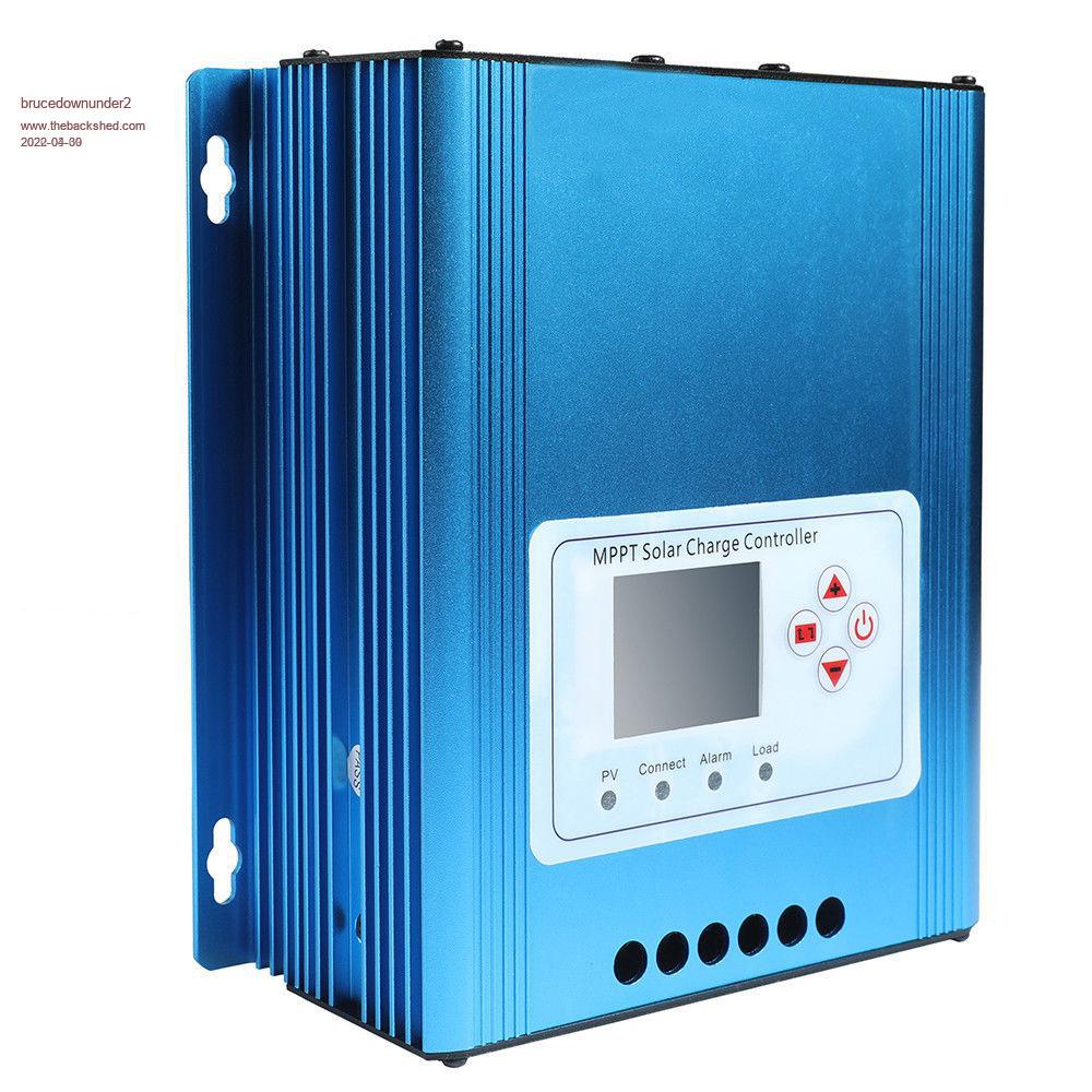 � 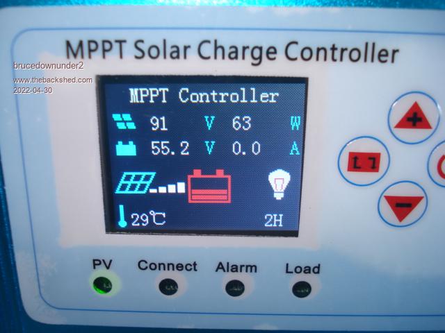 Edited 2022-04-30 11:19 by brucedownunder2 Bushboy |
||||
| morgs67 Regular Member Joined: 10/07/2019 Location: AustraliaPosts: 78 |
I had a quick look around the net, it seems to have been around in 2018 but not so much now. This may or may not be of help: https://www.tuntoenergy.com/aluminium-alloy-30-50-60a-home-mppt-solar-charge-voltage-controller-inverter It does have a sort of description of the settings. Tony |
||||
| brucedownunder2 Guru Joined: 14/09/2005 Location: AustraliaPosts: 1548 |
Thank You , Tony . I'll save that link , but I'm fairly sure that the problem is in passing the PV power through the unit ,into the battery. As, I've not seen more than 50 odd watts on its display -whereas , my E-smart 3 unit was passing some 1.3+ Kw. I've been in touch with the factory (or distributor), and after name e-mails have given up !!. At somewhere around $150 ,it all became more than I cared to contest. - I was wondering if someone had past experience with home repairs , like replacing the Mosfets or particular diodes, Etc. or a circuit ,ha, ha, lot of laughs.... Anyhow ,, I thank You for your interest, Bruce Pickers Bushboy |
||||
| Murphy's friend Guru Joined: 04/10/2019 Location: AustraliaPosts: 678 |
While I have never seen this type of inverter, the little symbols are not too hard  . .The one on the right means power on/off The one on the left steps through the menu pages I would guess The top & bottom arrows select items from the selected menu page. When you connect those things, always connect the battery first, preferably initially through a resistor to avoid the 'splat' of big capacitors charging up. |
||||
Revlac Guru Joined: 31/12/2016 Location: AustraliaPosts: 1282 |
I remember this charge controller was a bit difficult to figure out before, there was a video, but hard for me to see the details on that one. CPE 60A MPPT I still have a few pages of the user manual you sent me, perhaps I can resize and post them here if thats helpful. Edited 2022-04-30 21:23 by Revlac Cheers Aaron Off The Grid |
||||
| brucedownunder2 Guru Joined: 14/09/2005 Location: AustraliaPosts: 1548 |
Thank You, Aaron. (I tried phoning you yesterday, but you were out on your tractor ?. Anyhow, I remember that back shedder posting about the "Blue" controller, . He knew a lot about them ,but has disappeared, maybe another "back shedder" will know of the guy and advise us. I reckon mine is ok, except for one or two components that may have failed ,,,, if,,, I inadvertently connected something wrong when I first bought it --some years ago. I try calling you again today , I've been having trouble accessing the "backshed" on my I-pad lately, something to do with passwords,I'll sort that out. Bruce Bushboy |
||||
| brucedownunder2 Guru Joined: 14/09/2005 Location: AustraliaPosts: 1548 |
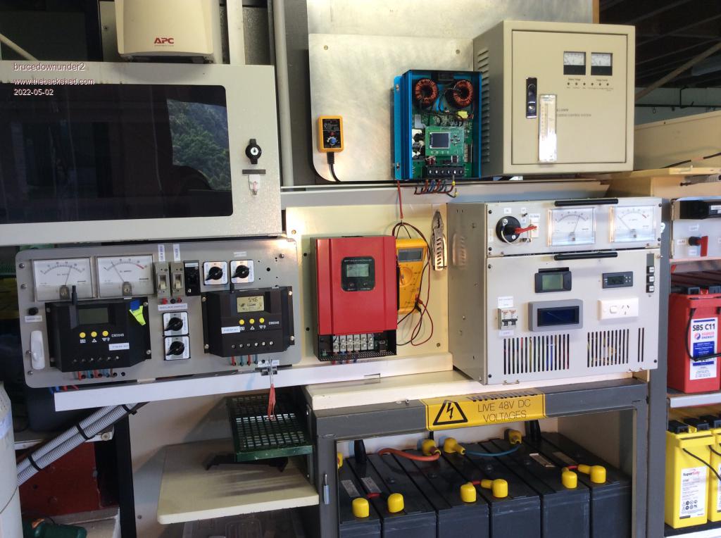
I'll attach a photo shot of the controller showing that it is seeing around 300 watts of power . But , it's not being directed into the battery, it shows 0 watts into the battery. (Aaron ,is your phone still un-available ?). Anyhow , I don't think I can do much about this controller until I find out what part needs replacing. I'm sure it's something I might have done long time back ,but put it on the shelf for later attention. (which is now,lol.) any clues ? thanks, Bruce 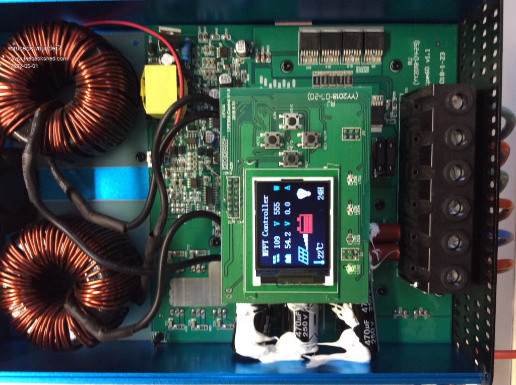 Bushboy |
||||
| Revlac Guru Joined: 31/12/2016 Location: AustraliaPosts: 1282 |
Hi Bruce, Yes phone is still on, had some dropped signal yesterday, and not much today but should still be working. Been thinking about this controller last knight and this morning. Now I see the photo of its innards, thanks will take a closer look. Just noticed it says 555 Watts, can you check the cable between the charge controller output and the battery with a clamp meter? The Amps out is 0 on the right hand side of the screen, I believe this will only show Amps out if the Load output connection is in use, you would have a to have A 48v light or something on the load terminal and turn it on or off via the button on the left....I think, better still check that output with a volt meter first, then try pressing the button on/off. The load out terminals should not really be used for anything, I have been warned by a few different Sellers not to use the load out terminals, it is mentioned in the manual do not connect an inverter to this terminal. So I think the Amp on the screen will remain at 0 and the battery can still be charging, seen as watts in....I think, but could be wrong.  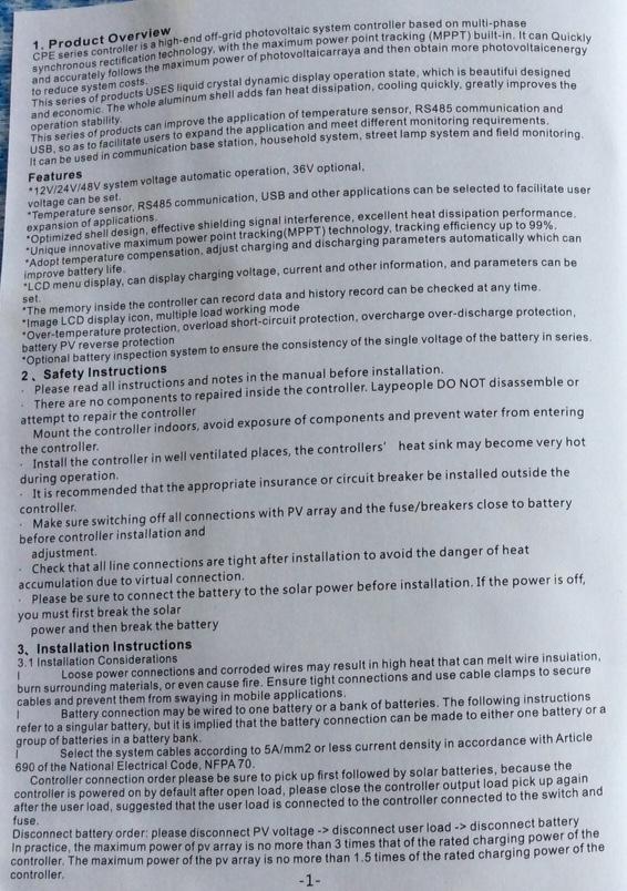 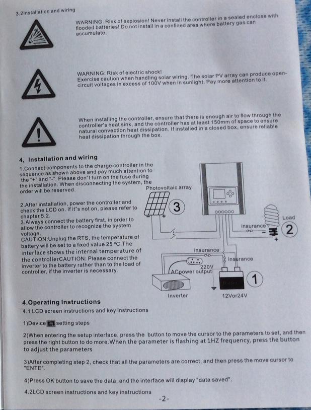 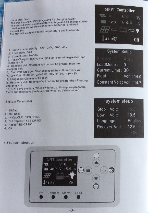 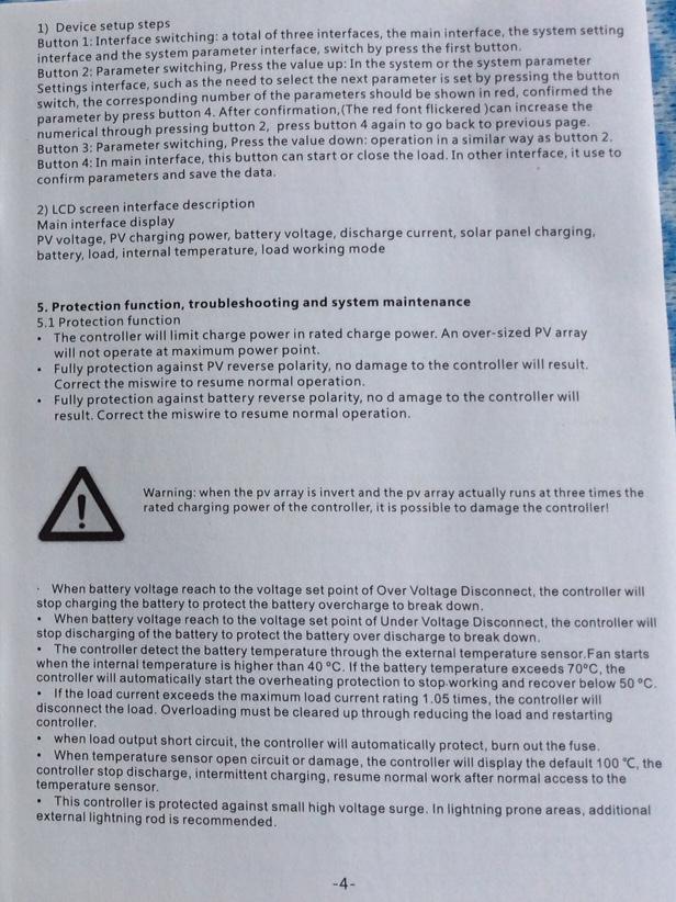 Text is not all that clear, but it will do. Edited 2022-05-01 13:52 by Revlac Cheers Aaron Off The Grid |
||||
| Godoh Guru Joined: 26/09/2020 Location: AustraliaPosts: 675 |
Hi Bruce, just below the screen and between it and the screw terminals there appear to be a couple of blade fuses. Have you checked them? Pete |
||||
| brucedownunder2 Guru Joined: 14/09/2005 Location: AustraliaPosts: 1548 |
Hi Aaron , Pete . �And of course the lots more that are interested, thank you. �First Pete, yes, they were the first ,long time ago , that got checked with a multimeter, plus pulled them for inspection-all appeared OK,thank You. Aaron , hi mate, was worried about your phone, living in the sticks is a bit dicky when the phone won't work... (I remember when I lived up in the jungle of Mt.Hargen ,in PNG,. I had a Codan HF with a long wire antenna ,which I had to tie a rock on , and haul it high into a tree. �-It was the only comms back to Port Moresby, who then telephoned the helicopter pilot to let him know we had run out of food and needed a lift to the distant pub, .Need-less to say, we never showered first ,it was straight into the bar for a few "Greenies".) back to earth,,,,, OK, Aaron, I'll check the load ,but I've never connected any load to that o/p. (But ,I'll check the programme to see if I have it on zero ), Hardly unlikely to effect it's o/put,as nothing is connected !. I just connected the power and switched it on ---- well, something caught my eye, it went to Kw output for a microsecond, yes, as if it was working charging the battery ,even though it was too short a period to see that , but , I think it tried to pass the power ,then went open again ???? --- So, thats the latest observation.... Bye the way , thanks for the written instructions, I have them also. �I'm getting sure it's a Mosfet or something very close ,,, as nearly all the controllers faults , I've heard about ,,are around this area ??? Thanks guys, it's been a good response --for everyone .. Bruce Edited 2022-05-01 16:01 by brucedownunder2 Bushboy |
||||
| Godoh Guru Joined: 26/09/2020 Location: AustraliaPosts: 675 |
Hi Bruce, it seems odd that the controller is showing watts on the screen, when nothing is going out. Does it run hot?. I am thinking you may be on the right track as far as mosfets go, they tend to short out a lot when they go to mosfet heaven. So maybe a shorted mosfet would still allow it to show a power reading. Looks like the mosfets are on the bottom of the board. But the solder connections appear to be on top, at least that is what you photo appears to show. What sort of readings have you got from them? Pete |
||||
| brucedownunder2 Guru Joined: 14/09/2005 Location: AustraliaPosts: 1548 |
Thanks , Pete. Yes, output is around 1-1.6 Kw this morning . Aaron and myself seem to think it still shows the "available" output, (if all was working OK ), I put my clamp meter on the output and other parts , but 0 is the reading... Anyhow, I'll be removing the from main board one of these days and expect to see the rear with the Mosfets,,which I can then measure. I suspect faults in this area. I sent an e-mail to the distributor ,or manufacturer ? ,,so waiting for a reply on the availability of a New e ???. I'm wiring some unfinished projects today, so just keeping an eye on faulty unit. Regards, Bruce. Bushboy |
||||
| Revlac Guru Joined: 31/12/2016 Location: AustraliaPosts: 1282 |
There seems to be a short burst of power from the controller to the batteries when it is switched on and solar is connected, then a fault (perhaps over voltage) is triggered and then it shuts off. I guess this indicated that it is trying to work and one set of fets are likely to be working for that to happen, the other set of fets or the driver maybe not working as they should, or the voltage sense section. Will wait and see what the response is from the manufacturer. Cheers Aaron Off The Grid |
||||
| wiseguy Guru Joined: 21/06/2018 Location: AustraliaPosts: 1297 |
Hi Bruce, as an outsider looking in I am not convinced the unit is charging at all. Aaron suggested a clamp meter to check if any current is actually flowing - it was a very good suggestion. Did you try that and if so what did you find? It looks like either the Watt meter or amp meter or both might be lying. I also think that the unit cannot predict the wattage that is/would be available but I am sure it can/should measure and report it whilst it is delivering that power. My advice before going too far towards swapping FETs etc is to check the supply voltages to the electronics, especially the measuring part (may be an op-amp or active type current sensor) as the measuring part appears to tell lies. There are 4 x surface mount T0220 packs with 7 pins and some others directly below the upper control panel and are probably part of the power path? these are easily accessible but difficult to ascertain if 1 is faulty if paralleled and maybe there are still others mounted/hidden underneath the pcb. The 550W but zero amps says a lot also, is it really delivering that 1.6kW? a clamp meter is the best and simplest way to confirm. If at first you dont succeed, I suggest you avoid sky diving.... Cheers Mike |
||||
| brucedownunder2 Guru Joined: 14/09/2005 Location: AustraliaPosts: 1548 |
 Kl Ok Mike. Sorry, lost my post, so here goes again.. I,m waiting on a replacement board for that controller,and will attempt to repair the faulty one. Thanks for your input, have done the clamp meter and other tests ,but the stuff at the back will have to wait. Thanks ,Mike, hopthis finds you well, Bruce Bushboy |
||||
| Revlac Guru Joined: 31/12/2016 Location: AustraliaPosts: 1282 |
The Amp measurement is something I would like to test, if it works...on the the battery charging output or on the load output terminals, or if it works at all. The load output terminals are often seen on a lot of those little 12-24v $20-$45 pwm charge controllers, not so often seen on big MPPT units that I'm aware of.....its in this one to add confusion.  They look a bit like D2PAK7 TO?263 7 LD or something, the first time I looked at this type of ic and saw one data sheet showing a mosfet in this package, it looks much the same, so pin 1 is the gate, in the photo it appears it may be connected on the other side of the board, there is some interesting mosfets in this type of package and might be an option for future builds......perhaps. The op amp might be one of those little 8 pin ic's, I replaced a cracked one on another charge controller... Thanks Mike, we will investigate further. Strange, received a Fatal error posting this. Edited 2022-05-02 22:56 by Revlac Cheers Aaron Off The Grid |
||||
| brucedownunder2 Guru Joined: 14/09/2005 Location: AustraliaPosts: 1548 |
First up , thanks for the help with this controller problem . The blue one . I got adventures and pulled it apart , after getting no help from the seller. So , I got to the. Boards and removed the small screen info board, held to the main board with multiple pins. After inspecting for hot areas,loose solder,any obvious heat or solder damage, I re assembled it to it,s sockets. This is where I made my mistake, I mis aligned. The group of fine pins and one side of the group was not in it,s socket. Sort of down one side of the socket. Switching on the unit , it just started to flash on and off repeatedly. I removed it and inserted it correctly ,but unfortunately, the damage has been done and blank,no indication of any screen info at all. I have power ,checking with my meter, at the terminal block and other components on the board. No switch on this controller , so the terminal block is the only clue to power being on. I can,test for reset or any thing ,really ,as I have no screen now... Any one with knowledge of these controllers,please let me know.. Thank you Bruce Bushboy |
||||
| cs41 Newbie Joined: 08/08/2016 Location: AustraliaPosts: 28 |
Hi Brucedownunder2. Was reading an old post re Dunlite wind gens and noted that you worked in PNG on Dunlites. I probably was there about same time ( 1965 - 1981 ) with telecom there and would be interested in swapping notes if you have time. Probably worked on the same sites on mountain op repeaters... Mt Otto, My Kerigomna, etc etc. Pleased reply direct : cschulz41@tpg.com.au as my email has changed from old ISP (Squirrel). Best Regards Colin S. |
||||
| brucedownunder2 Guru Joined: 14/09/2005 Location: AustraliaPosts: 1548 |
Hi Colin, Nice to hear from you, I was there for 3 years on Pt 10.?. Did 36 sites all over the place, from Vanomo up near the border to Bougainville, and Fly River site. Based in Moresby and Rabaul, mostly microwave, but all other projects , em TV, tropposcatter maintenance, Geruhu earth station, Manus Is.work . I led my mates from radio lines ,back in Qld. , working mainly on the radio side , with Ian Jennis ,rigger co from Perth , doing the tower work and lifting the dishes..my local boys from villages , did the labor, we helicopter camped for up to 10 days , then back to town for a week,s scrub up. I,m retired now, living Gold Coast hinterland on a mountain overlooking the Gold Coast. Property here keeps me. Busy, have windgennie, worked on the png wind genies, but mainly solar. If you get to Gold Coast , look me up , only half hour from the surfers paradise. Cheers, Bruce Bushboy |
||||
| cs41 Newbie Joined: 08/08/2016 Location: AustraliaPosts: 28 |
Hi Bruce, Good to hear from you with some notes on your PNG days. My first posting was Rabaul (1965) and loved it there. Later based in Lae and then P&T HQ Port Moresby. Worked on most radio sites around the country so saw a lot of different places. Last I saw of Ian Jennis was in Samoa where he refurbished their 300 ft AM Broadcast tower. Maybe you worked on the Madang - Manus Tropo scatter link... I did the final signoff on commissioning tests for PNG Telecom. on that. Also worked on the Lae - B'Ville tropo links which went through Rabaul. Great memories. After PNG we went to Vanuatu for 7 years with their telecom and then later 7 years in Samoa as Chief Engineer for their Telecom. If you like we can carry this on off this site ?? cschulz41@tpg.com.au We have settled in Nambour so a bit north of you. Thanks again cs. |
||||
| The Back Shed's forum code is written, and hosted, in Australia. | © JAQ Software 2026 |
