| Author |
Message |
mason

Regular Member

Joined: 07/11/2015
Location: CanadaPosts: 86 |
| Posted: 02:41pm 08 May 2022 |
 Copy link to clipboard Copy link to clipboard |
 Print this post |
|
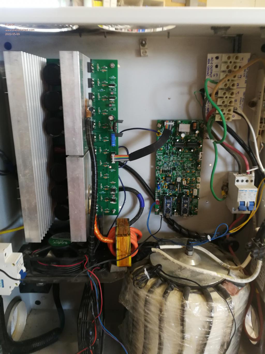
Hi Poida, just wondering if you could point me in the right direction, I've made your power board and the nano control card, when I fire it up with a low amp power supply no toroid it seems to work, when I put my battery bank and the toriod on it and then fire it up alls that happens is the light on the nano just flickers.
I was going to try using a different nano card.
 |
| |
poida

Guru

Joined: 02/02/2017
Location: AustraliaPosts: 1480 |
| Posted: 05:41am 09 May 2022 |
Copy link to clipboard |
Print this post |
|
I made a few errors with the power board in my first PCB attempt.
Did I send you one of these boards?
OR did you make the PCB from the gerber file?
It seems that you got some boards made.
(I deleted the instructions to fix errors with my first version power board)
You have an oscilloscope? it will be handy.
disconnect the nanoverter
apply 50V to the power board
check if about 17V is across C9 and C10
Edited 2022-05-09 16:20 by poida
wronger than a phone book full of wrong phone numbers |
| |
poida
Guru
Joined: 02/02/2017
Location: AustraliaPosts: 1480 |
| Posted: 06:28am 09 May 2022 |
Copy link to clipboard |
Print this post |
|
which versions firmware is used for both nanos?
Edited 2022-05-09 16:28 by poida
wronger than a phone book full of wrong phone numbers |
| |
mason
Regular Member
Joined: 07/11/2015
Location: CanadaPosts: 86 |
| Posted: 01:41pm 09 May 2022 |
Copy link to clipboard |
Print this post |
|
Poida, I'm using Arduino V1.8.7
Nano2_5_ac_current_sensor_dc_signal
Nano_1_v7_no_bessel. Set for 60hz
C9 17.5v
C10 17.5v roughly |
| |
mason
Regular Member
Joined: 07/11/2015
Location: CanadaPosts: 86 |
| Posted: 05:21pm 09 May 2022 |
Copy link to clipboard |
Print this post |
|
maybe I should just order the pico control card less parts to check lol, I had a nano hooked up to a mad power board last year and everything was working fine, shut it down for 6 months fired it back up yesterday and it poped 12 fets so I had your power board on the shelf put that in and changed the nano control card. I have both types of switches on it , so I turned the power switch on and the nano light just flickered shut that switch off and hit the momentary switch and a couple seconds later fried 6 fets , 80 amp breaker triped..
So I think its the nano card most of the bits are from China so could be anything. |
| |
poida
Guru
Joined: 02/02/2017
Location: AustraliaPosts: 1480 |
| Posted: 09:20am 10 May 2022 |
Copy link to clipboard |
Print this post |
|
I did find crap LM7805 (or was it LM7812..I think the latter) regulators from China.
I ended up getting proper ones from our elec hobby store
at 3x the price and they worked.
Do you have an oscilloscope?
It will show if correct drive signals are being generated
and then sent to the the TIP41/42 pairs
The picoboard is far easier to get working due to the smaller
parts count. IF you are not using the two NTC and fan drives you save
a few more parts.
Good to see 17.5V on those caps. That is one thing
that is needed.
Have you checked all 4 legs of the full bridge?
check all power FETs...but 6 are in parallel.. so we check
the Gates are high resistance, maybe 9K
Check for the body diodes
If you power the power board without the control board, the current draw
is about 40mA or something at 50V. If it's rather more then we might have a power board
issue.
It's hard to help via remote messages.
wronger than a phone book full of wrong phone numbers |
| |
mason
Regular Member
Joined: 07/11/2015
Location: CanadaPosts: 86 |
| Posted: 11:15am 10 May 2022 |
Copy link to clipboard |
Print this post |
|
I'll check those things you mentioned, I have a old oscilloscope and a hantek but don't have the skills you have with them.
I'm still trying to figure out why I get a good AC signal from the power board when I use my power supply, I have it set at 50v .7amps and the nano turns on no problems.
Yeah it's hard to help when you don't have the product in front of you. Lol
I appreciate the help. |
| |
poida
Guru
Joined: 02/02/2017
Location: AustraliaPosts: 1480 |
| Posted: 05:21am 11 May 2022 |
Copy link to clipboard |
Print this post |
|
good to know you have a scope
It might be vital for proving pwm output from control boards
Next could you show me the config information for
nano2?
connect to it with a serial/usb cable and the Arduino program,
send the character ? to it and copy the response showing current settings
I wonder if it's not configured well enough to run from the battery
It could be low voltage shutdown is set a bit too high or something.
wronger than a phone book full of wrong phone numbers |
| |
mason
Regular Member
Joined: 07/11/2015
Location: CanadaPosts: 86 |
| Posted: 07:29pm 11 May 2022 |
Copy link to clipboard |
Print this post |
|
You know when I have the nano plugged in then I start up the Arduino software a totally
different codes comes up ( Nano 2-1 ) don't know where that's coming from but when I look at the serial screen all my settings are there, I deleted all old versions of Nano code and reprogrammed Nano 2 with the current version. I'll try it again after I hear from you. So this is what I set everthing to
15:26:12.830 ->
15:26:12.830 -> heat sink temp = -268 degC ch.2
15:26:12.830 -> toroid temp = -273 degC ch.7
15:26:12.830 -> 1 - cal. DC volts nan -> nan V ch.1
15:26:12.830 -> 2 - cal. AC current nan -> nan V ch.6
15:26:12.876 -> 3 - cal. ACI offset nan ADC counts
15:26:12.876 -> 4 - cal. DC current nan -> nan A ch.3
15:26:12.876 -> 5 - cal. DCI offset nan ADC counts
15:26:12.876 -> 6 - cal. AC output nan -> nan V AC ch.0
15:26:12.876 -> N - Toroid NTC offset 0 degC
15:26:12.876 -> 7 - Toroid fan ON 70.00 degC
15:26:12.876 -> 8 - Toroid fan OFF 65.00 degC
15:26:12.876 -> 9 - Toroid shutdown 80 degC
15:26:12.876 -> P - H.S. NTC offset -5 degC
15:26:12.876 -> B - H.S. fan ON 50.00 degC
15:26:12.876 -> C - H.S fan OFF 40.00 degC
15:26:12.876 -> D - H.S. shutdown 75 degC
15:26:12.876 -> E - AC output low limit 200 V
15:26:12.876 -> F - LV cutoff voltage 47.0 V
15:26:12.876 -> Q - LV time below 5.0 seconds
15:26:12.923 -> A - Restart voltage 49.0 V
15:26:12.923 -> G - over current limit 20.0 A
15:26:12.923 -> H - enable/disable DC LV cutoff OFF
15:26:12.923 -> I - enable/disable over current cutoff OFF
15:26:12.923 -> J - enable/disable AC under volt cutoff OFF
15:26:12.923 -> K - enable/disable H.S. over temp cutoff ON
15:26:12.923 -> L - enable/disable Toroid over temp cutoff ON
15:26:12.923 -> M - enable/disable LCD backlight ON
15:26:12.923 -> Z - zero E2PROM
15:26:12.923 -> Y - put defaults into E2PROM
15:26:12.923 -> |
| |
poida
Guru
Joined: 02/02/2017
Location: AustraliaPosts: 1480 |
| Posted: 02:41am 12 May 2022 |
Copy link to clipboard |
Print this post |
|
I assume you have a minimal build here without
thermistors for heatsink and toroid, no DC current sensor, no AC current sensor
It should run fine just as long as you have
the AC voltage feedback in place.
I would check the AC feedback voltage and prove it's about 2.5V AC
when the feedback transformer is fed your desired output voltage.
Is it 120V or 240V?
I would disable all the cutoff reasons
from H to L inclusive
It appears you have no thermistors connected to the two inputs.
These may be giving high "temperatures" from EMI
and then the high temp cutoff code triggers..
These are enabled at the moment
IF you do not want to use the thermistors, put a 10K resistor across each
of the inputs. They will then read 25 C and not let EMI in via those pins.
It would be good to calibrate the DC volts for a start
power the board but don't let the inverter run and measure voltage
choose 1 from menu and tell it the voltage
Finally, I found the inverter run/stop input to be effected by EMI.
I put a 1uF cap across the pins and it settled down well.
wronger than a phone book full of wrong phone numbers |
| |
mason
Regular Member
Joined: 07/11/2015
Location: CanadaPosts: 86 |
| Posted: 07:14pm 12 May 2022 |
Copy link to clipboard |
Print this post |
|
Hi Poida, I tried those settings on two of the three cards I made
The third card I never tried at first but I thought what the heck ill try it,
Turns out this card worked the only thing that doesn't work is the stop run switch had to use the momentary switch, and the only thing different about this card is that the Nanos are soldered directly to the board. |
| |
poida
Guru
Joined: 02/02/2017
Location: AustraliaPosts: 1480 |
| Posted: 11:33pm 12 May 2022 |
Copy link to clipboard |
Print this post |
|
so you have a working inverter now?
Maybe there is a problem with component(s) on the other boards.
wronger than a phone book full of wrong phone numbers |
| |
mason
Regular Member
Joined: 07/11/2015
Location: CanadaPosts: 86 |
| Posted: 11:48pm 12 May 2022 |
Copy link to clipboard |
Print this post |
|
Yes it's working now thanks a lot for your help.
Yeah I think it's maybe the 21844 ICs. |
| |
