
|
|
Forum Index : Electronics : Build a High Current DC SSR
| Author | Message | ||||
| Solar Mike Guru Joined: 08/02/2015 Location: New ZealandPosts: 1123 |
Decided to make some DC load switches for 12\24 volt batteries in the field. I wanted something that will be isolated from the control system and allow up o 50 odd amps switching. Most of my battery chargers have a small low volts output relay or a switched output when the battery gets low; I can use this signal to turn off any loads rather than flatten the battery to death. High side switching is also required so battery 0v is common for charger\loads\control systems etc. Here is design #1, for 12v batteries, uses 3 smd mosfets with a combined Ron of only 0.001r, so any losses will be pretty low at 30amps loads currently in use. The driver is an internal voltage generator chip designed for SSR relay use, so makes things pretty simple. Note the switching rate is very low, you cannot use this design for PWM applications. 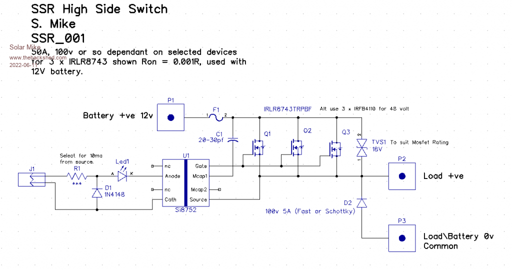 PCB: 80 x 65mm 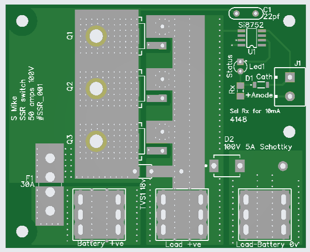 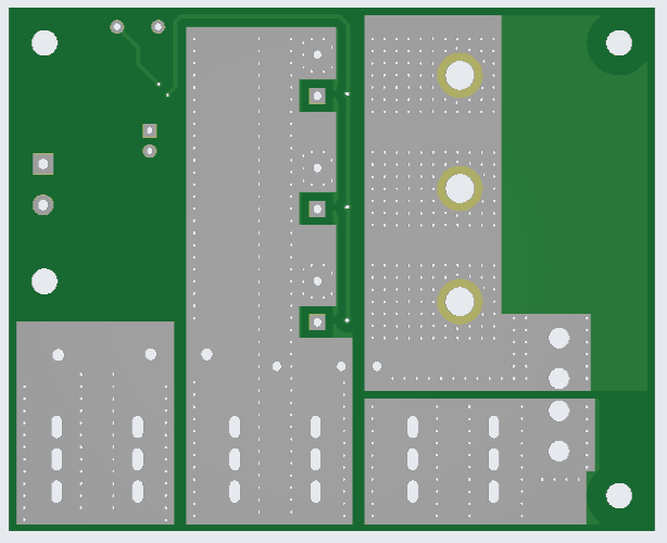 Will clone this for a Ver2, to use 2 x larger mosfets for use at higher voltages eg 100V then post the gerbers. Cheers Mike |
||||
| Solar Mike Guru Joined: 08/02/2015 Location: New ZealandPosts: 1123 |
Here is Ver 2, track spacing increased to 1.4mm and two only larger mosfets used as these are easier to get in the higher voltage ranges. Nominal 150V rating and 50 amps; extra wire can be soldered to tracks for increased current on the 1oz pcb. Power devices bolt to top of the pcb, no heatsink required for currents approx 30A. I have removed the auto type 30a fuse, these are useless at any voltages over 50V as they can flash over should it blow. Top: 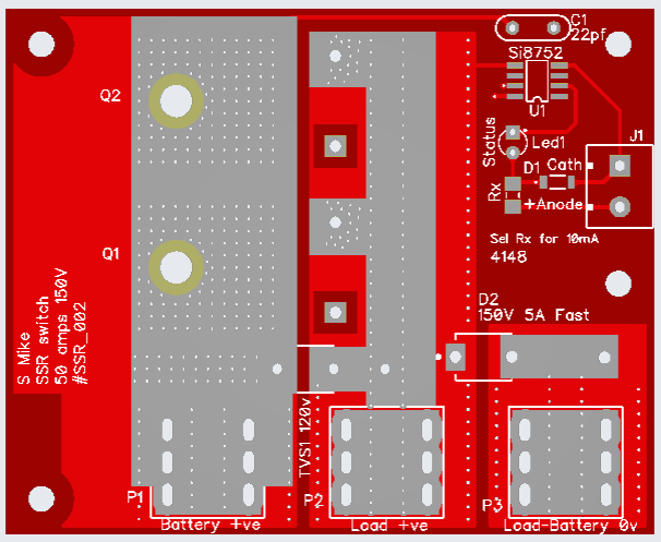 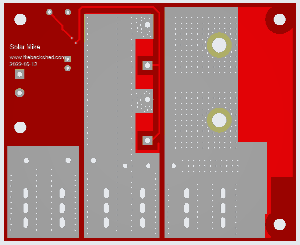 Gerbers_SSR001.zip Gerbers_SSR002.zip Cheers Mike |
||||
| Gizmo Admin Group Joined: 05/06/2004 Location: AustraliaPosts: 5012 |
Nice work Mike. With all the fake SSR's on ebay, its a good idea to roll your own. Glenn The best time to plant a tree was twenty years ago, the second best time is right now. JAQ |
||||
| flyingfishfinger Senior Member Joined: 12/09/2020 Location: United StatesPosts: 102 |
Oh, nice. Was looking for just such a thing! I see DipTrace schematics, very cool. Couple observations: - The MOSFETS are TO220 packages, right? I don't see a 3rd through-hole on the PCB - I would still connect the D pin even though you are using the body / tab for that. Are you cutting them off? - You have your indicator LED in series with the FET driver's LED. The max Vf for the internal LED is 2.35V. If you're going for 10mA current and your indicator LED has a similar Vf, you will NOT be able to drive this with a 3.3V MCU. I would suggest the Si8751 with a 10k resistor on the TT pin, that way the input is voltage agnostic. The downside is then you need a VDD input, but your current version works fine with a 5V Arduino. Would you be willing to share the Diptrace source for this so I can make the above tweaks? Cheers, R |
||||
| Solar Mike Guru Joined: 08/02/2015 Location: New ZealandPosts: 1123 |
I am using both SMD packages and TO220, so the pcb mosfet foot print doesn't have a third D pin, I cut them off for the TO220 devices. They bolt or solder to the tinned pcb track, if a heatsink is required then I place a layer of SilPad material under the board to insulate from the heatsink, heat conducts through to the bottom layer via the numerous via's. Quite right, for 3.3v drivers the other si8751 version could be used or driven via a logic level mosfet. I will only be using this with 5v CPU's and only have si8752 devices on hand. No problem, providing you post the changed version here, so others can use it. DipTrace_SSR_1_2.zip Cheers Mike |
||||
| flyingfishfinger Senior Member Joined: 12/09/2020 Location: United StatesPosts: 102 |
Sure, happy to share changes. What terminals go on those connector pads? R |
||||
| Solar Mike Guru Joined: 08/02/2015 Location: New ZealandPosts: 1123 |
I used these PCB 4 Welding Terminal There are numerous other sellers with 4mm pcb brass\copper terminals, the ones above are brass, some will sell you steel with tin plating even though they may say "Brass or Copper" Mike |
||||
| flyingfishfinger Senior Member Joined: 12/09/2020 Location: United StatesPosts: 102 |
Awesome, thanks. By the way, there's no schematic for the v2 in that folder, just for the v1 - can you check on that if you have a moment? Cheers, R |
||||
| Solar Mike Guru Joined: 08/02/2015 Location: New ZealandPosts: 1123 |
Circuit is the same, only change in mosfet type and the fuse removed. Mike |
||||
